

 LANGUAGE
 中文简体
中文简体 русский
 Français
 Español
 Português
 عربى
عربى


Motorized Take-Up Equipment Machine
A motorized Take up equipment machine is a specialized industrial device designed to automatically wind, store, and manage cables, wires, or filaments in an orderly manner. Powered by electric motors (such as torque motors or frequency-converted motors), it works with supporting components like reducers, tension controllers, and traversing mechanisms to ensure stable operation.
Its core function is to maintain consistent tension during winding, preventing cable damage from overstretching, kinking, or tangling. The motor adjusts speed and torque according to the cable’s winding diameter, synchronizing with upstream production lines or equipment movement to avoid disruptions.
Widely used in power cable production, construction, mining, and port machinery, it accommodates various cable types (power, communication, automotive) and specifications, with winding lengths up to 1000 meters for certain models. Features like automatic stop, spool switching, and safety guards enhance efficiency and operational safety, reducing manual labor and material waste.
- Technical Parameters
- Contact Us


Shanghai Yessjet Precise Machinery Co., Ltd.
Precision Machinery, Intelligent Solutions Powering Cable Production Worldwide
Shanghai Yessjet Precise Machinery Co., Ltd. was established in Shanghai with investment from
Taiwan
in 2002 as a professional manufacturer dedicated to the research and development of wire and cable
machinery.
In 2017, to expand the company's scale, Jiangsu Yessjet Precise Machinery Co., Ltd. was established with
investment
in Yixing, Wuxi, Jiangsu.
We specialize in designing and manufacturing high-performance production systems — from extrusion lines and automatic coiling machines to robotic palletizing solutions — helping customers achieve efficiency, flexibility, and sustainable growth. As Motorized Wire Cable Take-Up Machine Suppliers and MAutomatic Cable Take-Up Machine Manufacturers, we provide professional on-site installation and system commissioning services to ensure rapid equipment startup and stable operation. We also conduct operator training to guarantee efficient production line launch. Custom Automatic Wire Cable Pay-Off Equipment. For existing production lines, we offer customized retrofit solutions. Through partial upgrades or automated integration, we help clients enhance production capacity, precision, and intelligent capabilities to maximize return on investment.
View
More
We specialize in designing and manufacturing high-performance production systems — from extrusion lines and automatic coiling machines to robotic palletizing solutions — helping customers achieve efficiency, flexibility, and sustainable growth. As Motorized Wire Cable Take-Up Machine Suppliers and MAutomatic Cable Take-Up Machine Manufacturers, we provide professional on-site installation and system commissioning services to ensure rapid equipment startup and stable operation. We also conduct operator training to guarantee efficient production line launch. Custom Automatic Wire Cable Pay-Off Equipment. For existing production lines, we offer customized retrofit solutions. Through partial upgrades or automated integration, we help clients enhance production capacity, precision, and intelligent capabilities to maximize return on investment.
YESSJET
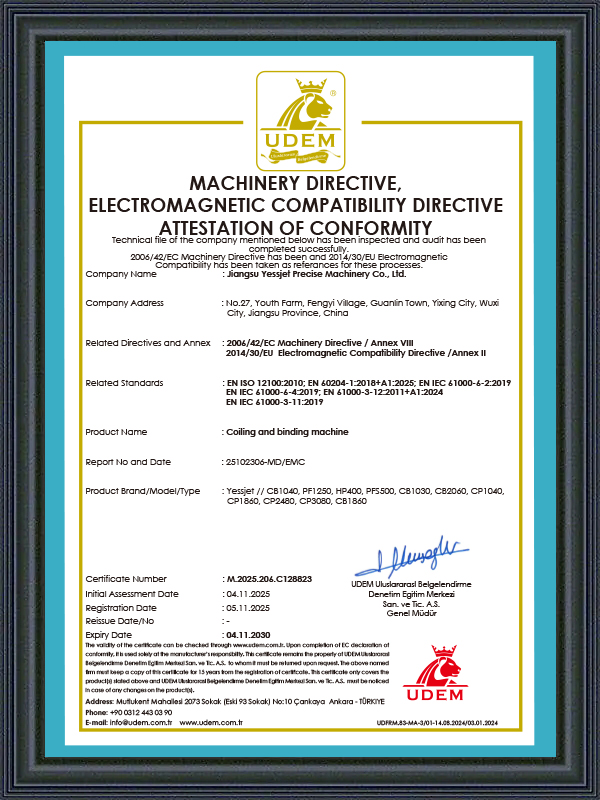
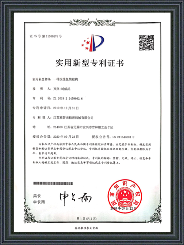
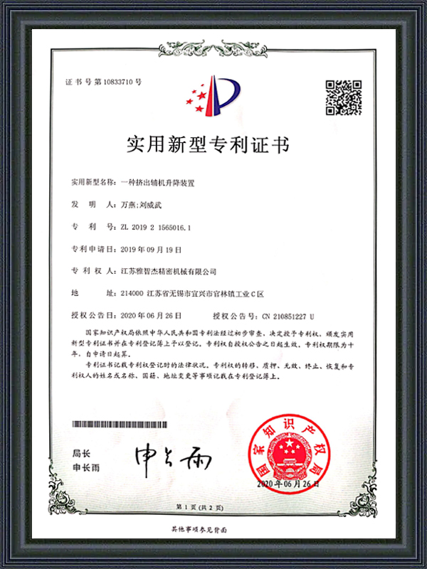
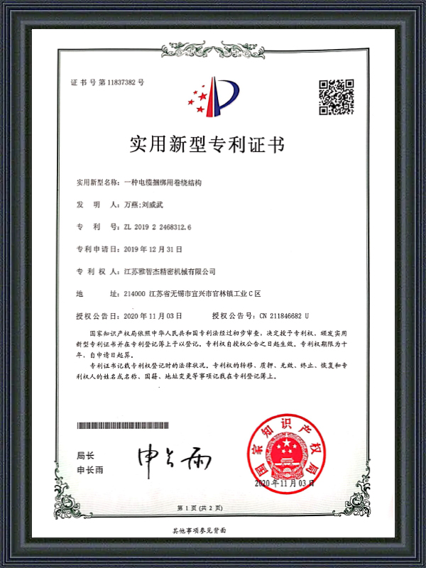
Honorary Certification
CERTIFICATE

Latest Updates
What'S News
-
Automatic Wire Winding Machine: How It Works & How to Choose the Right OneA single operator manually winding wire onto spools can process roughly 200–400 meters per hour. An automatic wire winding machine running at full speed handles that same volume in minutes — with zero variation in coil tension, zero misalignment, and no fatigue-related errors at the end of a shift....
-
Cable Insulation Extruder & Wire and Cable Extruder Machine: Full GuideBare copper goes in. Insulated, protected, ready-to-ship cable comes out. The machine that makes that transformation possible is the cable insulation extruder — and choosing the right one shapes every metre of cable your factory will ever produce. This guide covers how these machines work, what the...
-
Automatic Cable Labeling Machine: Cable Coil Labeling & Label Feeder GuideOn a cable production line running at full capacity, a single labeling station staffed by one operator can become the bottleneck that limits throughput across the entire packaging sequence. Manual cable coil labeling is slow, inconsistent, and—when the operator is fatigued or distracted—prone to c...
Industry Knowledge
Taper Tension Winding: Why Constant Tension Is the Wrong Strategy for Large Cable Spools
One of the most persistent misconceptions in cable winding practice is that maintaining a constant tension setpoint throughout the full spool build produces the best coil quality. In reality, constant tension winding on a Motorized Wire Cable Take-Up Machine produces mechanically unstable spools on large-diameter builds because the inner layers — wound at the beginning of the spool when the winding radius is small — are subjected to compressive loading from every subsequent layer wound on top of them. As the spool builds outward, the cumulative radial pressure on the innermost layers increases progressively, eventually exceeding the cable jacket's compressive yield strength and causing permanent deformation of the insulation at the layer interfaces. The deformation is not visible externally but produces elevated capacitance readings and potential dielectric weakness at the affected points.
Taper tension winding addresses this by deliberately reducing the winding tension as the spool diameter increases. The tension at any given winding diameter is set as a percentage of the starting tension, following a taper profile — linear or curved — that keeps the radial pressure on inner layers within acceptable limits throughout the build. A typical taper ratio for PVC-insulated power cable is 60–75%, meaning that the tension at the full spool outer diameter is 60–75% of the tension applied at the core. The exact taper profile is determined by the cable's jacket modulus, the spool geometry, and the maximum acceptable inner-layer compressive stress — parameters that require engineering calculation rather than empirical trial-and-error on production spools.
Implementing taper tension on an Automatic Cable Take-Up Machine requires the control system to track the current winding diameter continuously and apply the corresponding tension setpoint in real time. The winding diameter can be derived from the ratio of the traverse speed to the spool rotational speed — a calculation available in most modern servo drive platforms without requiring additional sensors. Shanghai Yessjet Precise Machinery Co., Ltd. configures taper tension profiles as part of the product recipe system on its Motorized Wire Cable Take-Up Machine range, allowing operators to store and recall the correct taper parameters for each cable specification without manual recalculation at the machine during product changeover.
Traverse Pitch Calculation and Its Effect on Spool Layer Stability
The traverse pitch — the lateral distance the cable advances per revolution of the winding spool — is the parameter that determines how densely the cable is packed across the spool flange width and whether the layer interfaces are geometrically stable. An incorrect traverse pitch produces one of two failure modes: pitch too tight creates overlapping layers where adjacent cable turns dig into each other under winding tension, causing jacket surface damage and irregular layer height that makes subsequent layers unstable; pitch too wide creates gaps between adjacent turns that allow upper layers to fall through and cross over lower turns during the winding process, producing the characteristic "crossed layer" defect that makes the spool unusable on automatic payout equipment.
The theoretically correct pitch for a single-layer wind is equal to the cable outer diameter plus a clearance allowance of 1–3% to accommodate OD variation across the spool length. In practice, the nominal OD used for pitch calculation should be the maximum OD specification limit rather than the nominal value, because pitch calculated at nominal OD will produce overlapping on cable that runs at the upper OD tolerance. For cables with OD tolerances wider than ±3%, a fixed pitch calculated from the maximum OD will produce visible gaps on cable running at nominal or minimum OD — in these cases, a closed-loop pitch adjustment system that reads the actual cable OD from a laser gauge and updates the traverse pitch in real time provides superior layer quality across the full production OD range.
Traverse Pitch Configuration by Cable Type
| Cable Type | OD Tolerance | Recommended Pitch Basis | Clearance Allowance |
| Building wire, single core | ±2–3% | Maximum OD specification | 1.5% |
| Multi-core flexible cable | ±4–6% | Real-time OD measurement | 2.0–2.5% |
| Armored power cable | ±3–5% | Maximum OD + armor wire height | 2.5–3.0% |
| Coaxial / data cable | ±1–2% | Nominal OD (tight tolerance) | 1.0% |
For multi-layer winding, the pitch calculation must also account for the layer-to-layer cross-over angle — the angle at which each successive layer reverses traverse direction at the flange. An excessively steep cross-over angle causes the cable to dig into the previous layer at the reversal point rather than riding over it smoothly, creating a raised edge bead at the flange that grows progressively with each layer and eventually prevents the cable from seating properly across the full spool width. Controlling the cross-over angle requires adjusting the traverse deceleration and reversal profile at the flange end-of-travel, which is a drive parameter setting distinct from the steady-state traverse pitch and must be configured independently for each cable OD range.
Spool Change Sequencing on Automatic Cable Take-Up Machines: Minimizing Scrap Length
The spool change event on an Automatic Cable Take-Up Machine is the transition that most directly determines how much usable cable length is lost per spool change cycle. During the change sequence — from the moment the full spool signals completion to the moment the new spool reaches steady-state winding tension — the upstream extrusion line continues producing cable that either accumulates in an accumulator buffer or requires the line to reduce speed. Cable produced during the accumulator discharge and line speed transition is frequently off-specification in wall thickness or conductor position due to the speed variation, and this length must be scrapped or downgraded. Minimizing this scrap length requires optimizing three interdependent variables: accumulator capacity, spool change cycle time, and the control handshake sequence between the take-up machine and the line master PLC.
The spool change cycle time on an Automatic Cable Take-Up Machine consists of several sequential steps, each of which contributes to the total changeover duration. Understanding the time budget for each step identifies where engineering investment in automation or mechanical design improvement delivers the greatest reduction in total cycle time and associated scrap length.
- Full spool detection and signal transmission: The meter counter reaches the target length, triggers the change sequence, and signals the accumulator to begin discharging — this step should take less than 200 milliseconds on a modern PLC-controlled system; relay-logic systems often introduce 1–3 second delays that consume accumulator capacity before the mechanical sequence even begins
- Cable cut and tail securing: The flying cutter or stationary cutter actuates, severs the cable, and the tail is secured to the full spool — total duration typically 1–3 seconds on automated systems; manual tail-tying extends this to 15–30 seconds and requires the line to stop completely
- Full spool removal and empty spool positioning: The spool carriage or turret rotates or indexes to bring the empty spool into the winding position — turret-style take-up machines complete this step in 3–6 seconds; single-position machines requiring forklift exchange take 2–8 minutes depending on facility layout and equipment availability
- Lead attachment and initial winding acceleration: The cable lead is attached to the new spool core, and the winding drive accelerates to match line speed — servo-driven take-up machines can complete this acceleration in 2–4 seconds; older DC drive systems may take 8–15 seconds to reach stable winding tension
The total scrap length generated per spool change is the product of the line speed and the sum of all steps during which the accumulator is discharging and the take-up is not yet winding at steady-state tension. At a line speed of 200 m/min, a 30-second total changeover time produces 100 meters of potentially off-specification cable per change event — a significant material cost on a line running multiple spool changes per shift. Reducing the changeover time to 8 seconds through turret take-up and servo acceleration reduces this to approximately 27 meters, a 73% reduction in per-change scrap that has a direct impact on production yield and material cost per kilometer of cable produced.
Tension Feedback Architecture: Dancer-Based vs. Load Cell-Based Control
Motorized Wire Cable Take-Up Machines use one of two primary tension measurement architectures to generate the feedback signal for the winding tension control loop: dancer roller position feedback or direct load cell tension measurement. Each architecture has distinct response characteristics, calibration requirements, and failure modes that make one or the other more appropriate depending on the cable type, line speed, and tension stability requirements of the application. Understanding the fundamental differences allows engineers to specify the correct system for new installations and to diagnose control performance issues on existing systems without defaulting to controller retuning as the first response.
Dancer-based tension control uses the position of a spring-loaded or pneumatically loaded roller in the cable path as an indirect measure of tension — the dancer displacement is proportional to the tension force when the dancer mass and spring or pneumatic preload force are known. The key advantage is mechanical simplicity and inherent accumulation capability: the dancer roller travel provides a buffer that absorbs speed transients without requiring the control loop to respond instantaneously. The limitation is that dancer position is an indirect tension measurement — it measures force at the dancer contact point, which can differ from the tension at the winding point due to friction in the cable path between the dancer and the spool, particularly on large-diameter cables with high bending stiffness that generate significant contact friction against guide rollers and eyelets.
Load cell tension measurement places a strain gauge force transducer directly in the cable path — either as an instrumented guide roller or as a reaction force sensor on a fixed guide pin — and provides a direct electrical signal proportional to the cable tension at the measurement point. Load cell systems eliminate the friction-induced measurement error of dancer systems and provide a higher-bandwidth tension signal that is more suitable for high-speed winding applications where rapid tension transients must be detected and corrected within individual winding revolutions. The trade-off is that load cells have no buffering capability — the control loop must respond to every tension transient, requiring higher control bandwidth and more careful PID tuning to avoid oscillation. Load cell systems also require periodic calibration to maintain measurement accuracy, as the strain gauge zero offset drifts with temperature and mechanical fatigue over time.
Winding Spool Mechanical Compatibility: Shaft Interface Standards and Load Ratings
A frequently overlooked source of winding quality problems on Motorized Wire Cable Take-Up Machines is mechanical incompatibility between the winding spools and the take-up machine shaft interface. Cable manufacturers typically accumulate a mixed inventory of spools from multiple suppliers over years of operation, with subtle dimensional variations in bore diameter, keyway geometry, and flange concentricity that cause problems on take-up machines with tight shaft tolerances. A spool with a bore diameter 0.3mm larger than the shaft nominal creates a clearance fit that allows the spool to run eccentric under winding tension — the eccentricity generates a once-per-revolution tension ripple that the control system cannot suppress because it is mechanically induced rather than process-generated.
The relevant spool mechanical parameters that must be verified for compatibility with a Motorized Wire Cable Take-Up Machine include bore diameter and tolerance, keyway width and depth, flange runout specification, and the spool's rated weight capacity at the maximum cable fill level. Spool weight capacity is particularly important on Automatic Cable Take-Up Machines with high traverse force capability — the winding tension applied across the full spool traverse width generates a significant bending moment on the spool shaft bearings, and exceeding the spool's structural rating can cause flange deformation that permanently damages the spool and creates a safety hazard when the loaded spool is handled by forklift.
- Bore diameter verification: Measure the bore diameter of new spool batches with a calibrated bore gauge before putting them into production service — accept only spools within ±0.05mm of the shaft nominal diameter for precision take-up applications; wider tolerances require tapered adapter sleeves that add complexity and potential for eccentricity
- Flange runout inspection: Check flange face runout with a dial indicator on a reference mandrel before first use and after any spool drop event — runout exceeding 0.5mm per 300mm flange radius indicates flange deformation that will cause traverse reversal timing errors and edge bead formation
- Maximum fill weight calculation: Calculate the maximum cable fill weight as the product of the spool's net storage volume (total spool volume minus core volume) and the cable weight per unit volume — verify that this value is below the spool's rated gross load capacity, which includes the spool tare weight, by a minimum safety factor of 1.5
- Keyway fit class: Specify a close-fit keyway (JS9/h9 or equivalent per ISO 286) for take-up applications rather than the normal-fit tolerances used for general power transmission — loose keyway fits allow spool rotation relative to the shaft during acceleration and deceleration, producing micro-slip events that create localized tension spikes
Retrofit Integration of Automatic Cable Take-Up Machines into Existing Extrusion Lines
Adding an Automatic Cable Take-Up Machine to an existing extrusion line that was originally designed for manual take-up involves control integration challenges that are often underestimated during the project planning phase. The extrusion line's haul-off speed controller was designed to operate as the terminal speed reference for the line — it sets the production speed, and all upstream equipment follows. When an automatic take-up machine is added, it introduces a second closed-loop control system at the end of the line that is also attempting to regulate cable tension through speed adjustment. Without proper coordination of these two control loops, they interact adversely: the haul-off increases speed in response to a tension drop signal while the take-up drive simultaneously reduces speed in response to the same tension drop, creating a sustained oscillation that neither loop can resolve independently.
The standard solution is to configure the take-up drive in torque control mode rather than speed control mode, with the haul-off drive remaining as the speed master. In torque control mode, the take-up drive applies a constant winding torque corresponding to the target tension setpoint, and the winding speed adjusts automatically to match the haul-off output speed — similar to how a passive brake provides constant resistance regardless of speed. The dancer roller position then serves only as a trim signal to adjust the torque setpoint, not as the primary speed reference. This control architecture eliminates the loop interaction problem because the take-up drive is no longer competing with the haul-off to control cable speed — it is simply providing a controlled resistance torque that the haul-off speed controller can drive against without conflict.
Founded in 2002 in Shanghai with investment from Taiwan and expanded through Jiangsu Yessjet Precise Machinery Co., Ltd. in Yixing, Wuxi in 2017, Shanghai Yessjet Precise Machinery Co., Ltd. has accumulated extensive experience integrating Motorized Wire Cable Take-Up Machines and Automatic Cable Take-Up Machines into extrusion lines built by a wide range of original equipment manufacturers. The integration engineering process begins with a control system audit of the existing line to identify the haul-off drive type, communication protocol capability, and available I/O for interlocking — followed by a defined integration architecture that specifies exactly how the take-up drive will receive its speed reference and how the dancer signal will be routed to avoid loop interaction. This structured approach has consistently reduced retrofit commissioning time compared to uncoordinated add-on installations where control interaction problems are discovered and resolved iteratively during production trials.
Quick Links
Product Categories
Contact Us
-
 [email protected]
-
 +86-0510-87258118
-
 +86-18888031330
-
 No. 27, Youth Farm, Fengyi Village, Guanlin Town, Yixing City, Jiangsu Province China.
Copyright © Shanghai Yessjet Precise Machinery Co., Ltd. Rights Reserved. Motorized Wire Cable Take-Up Machine Suppliers
