

 LANGUAGE
 中文简体
中文简体 русский
 Français
 Español
 Português
 عربى
عربى The device can automatically coil wires and cables into loops and then wrap them using materials such as PVC film, PE film, PP film, or paper tape. Automatic error detection: If the machine malfunctions, it will automatically identify the issue and alert the operator to ensure proper maintenance and...
View More
Fully Automatic Coiling Packaging Equipment Manufacturers
-
Product Fully Automatic Coiling & Wrapping Machine

-
Product Fully Automatic Coiling Binding & Wrapping MachineFully automatic coil binding machine is an industrial automation device used to automatically coil and bind (secure) wires, cables, hoses, etc. It automates the entire process from coiling, positioning, binding to output, significantly improving work efficiency and reducing manual labor.This machine...View More

-
Product Cable Heat Shrink Packaging MachineThe Cable Heat Shrink Packaging Machine is a reliable packaging solution tailored for cables, wire coils, and related components across power, communication, and industrial fields. Designed to simplify and enhance packaging processes, it operates through a precise "film application-heating-shrinking...View More

-
Product Auto-Wrapping Machine For Circular ObjectPut circular object on the machine can automatically wrap them. Usually PVC tape and other materials are used for packaging.Automatic error detection: When the equipment fails, it will automatically detect the error and send an alarm to remind the operator to ensure the normal operation and mainte...View More

-
Product Automatic Cable Spooler Coiling MachineThe equipment is capable of automatically wrapping wires and cables on plastic spools. Automated error detection: In case of a malfunction, the machine will automatically pinpoint the problem and notify the operator for proper maintenance and operation. Servo motor cable organization system: This sy...View More

Fully Automatic Coiling Packaging Equipment is an integrated solution for efficient coiling and packaging of various cylindrical and cable-type products, covering core models like Fully Automatic Coiling & Wrapping Machine, Coiling Binding & Wrapping Machine, circular object auto-wrapping machine, automatic cable spooler coiling machine, and heat shrink packaging machine.
It realizes full-process automation from material feeding, precise coiling, tight binding to wrapping or heat shrink sealing, eliminating manual errors and boosting packaging consistency. Suitable for cables, hoses, metal wires and other circular items, it adapts to different product specifications with adjustable parameters. This equipment cuts labor costs, enhances production efficiency and ensures neat, stable packaging, which is a reliable choice for manufacturing and logistics industries pursuing standardized operations.
Shanghai Yessjet Precise Machinery Co., Ltd.
Precision Machinery, Intelligent Solutions Powering Cable Production Worldwide
Shanghai Yessjet Precise Machinery Co., Ltd. was established in Shanghai with investment from
Taiwan
in 2002 as a professional manufacturer dedicated to the research and development of wire and cable
machinery.
In 2017, to expand the company's scale, Jiangsu Yessjet Precise Machinery Co., Ltd. was established with
investment
in Yixing, Wuxi, Jiangsu. Fully Automatic Coiling Packaging Equipment Manufacturers and OEM/ODM Fully Automatic Coiling Packaging Equipment Factory in China.
We specialize in designing and manufacturing high-performance production systems — from extrusion lines and automatic coiling machines to robotic palletizing solutions — helping customers achieve efficiency, flexibility, and sustainable growth. Fully Automatic Coiling Packaging Equipment Custom. Integrate all in-house product lines with external resources to provide clients with comprehensive services spanning process design, equipment selection, layout planning, installation and commissioning, and personnel training, ensuring projects achieve successful first-time startup.
View
More
We specialize in designing and manufacturing high-performance production systems — from extrusion lines and automatic coiling machines to robotic palletizing solutions — helping customers achieve efficiency, flexibility, and sustainable growth. Fully Automatic Coiling Packaging Equipment Custom. Integrate all in-house product lines with external resources to provide clients with comprehensive services spanning process design, equipment selection, layout planning, installation and commissioning, and personnel training, ensuring projects achieve successful first-time startup.
YESSJET
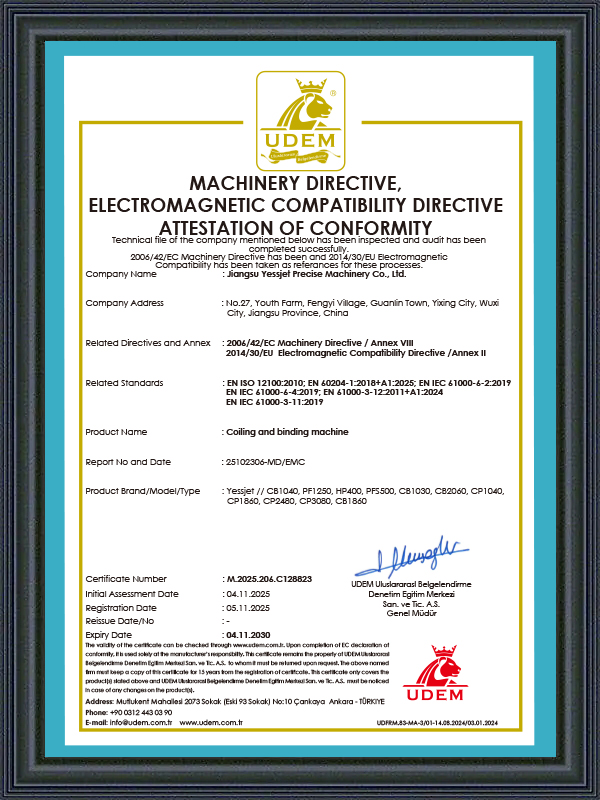
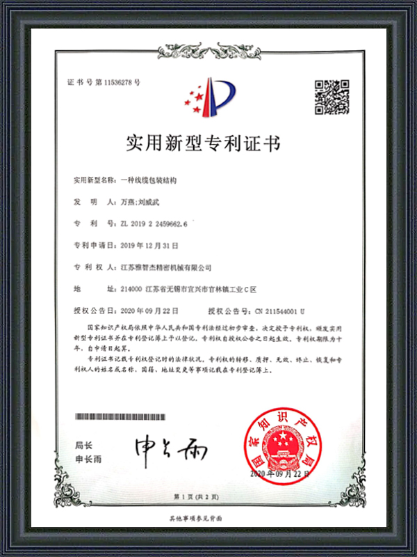
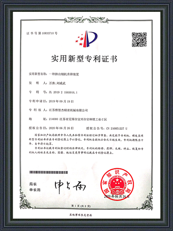
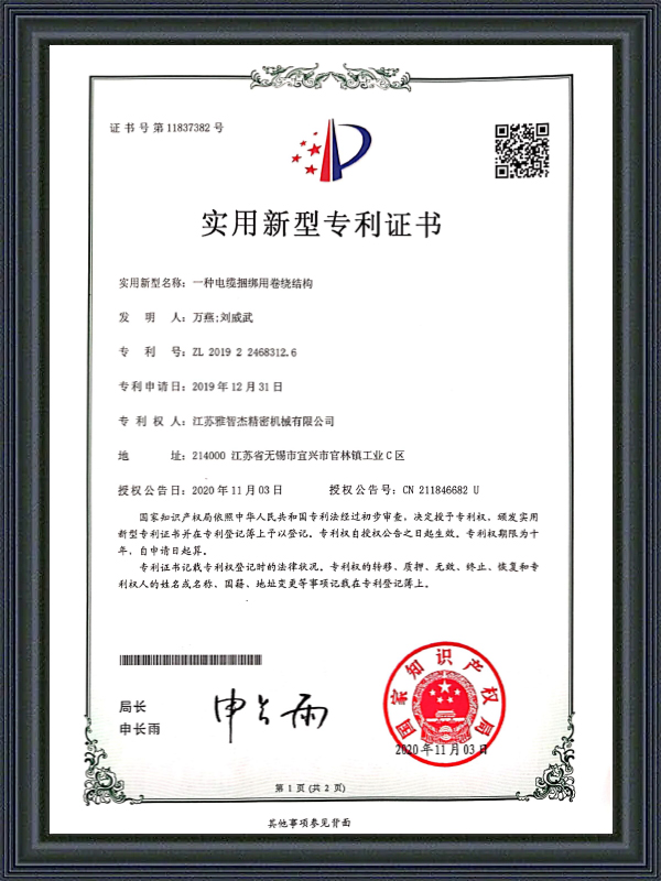
Honorary Certification
CERTIFICATE
Latest Updates
What'S News
-
Automatic Wire Winding Machine: How It Works & How to Choose the Right OneA single operator manually winding wire onto spools can process roughly 200–400 meters per hour. An automatic wire winding machine running at full speed handle...
-
Cable Insulation Extruder & Wire and Cable Extruder Machine: Full GuideBare copper goes in. Insulated, protected, ready-to-ship cable comes out. The machine that makes that transformation possible is the cable insulation extruder ...
-
Automatic Cable Labeling Machine: Cable Coil Labeling & Label Feeder GuideOn a cable production line running at full capacity, a single labeling station staffed by one operator can become the bottleneck that limits throughput across...
-
PP PVC PE Cable Extruder Machine: Multi-Material Guide for Cable ManufacturersSwitch a cable extrusion line from PVC to PP mid-run and two things will go wrong fast: barrel temperatures set for PVC's amorphous melt behavior will overshoo...
-
Automatic Cable Coiling and Wrapping Machine | PP Tape, Servo Motor GuideWhat Is an Automatic Cable Coiling and Wrapping Machine? An automatic cable coiling and wrapping machine combines two traditionally separate production steps —...
Industry Knowledge
Coil Geometry Control: Why Inner Diameter Consistency Matters More Than It Looks
In Fully Automatic Coiling Packaging Equipment, the inner diameter (ID) of a finished coil is rarely treated as a critical process variable — yet it directly affects downstream handling, retail display compatibility, and the mechanical behavior of the cable during payout. A coil wound with inconsistent ID — caused by mandrel expansion timing errors, inconsistent core clamping pressure, or variation in line tension during the initial winding turns — will produce a coil that sits unevenly on display hooks, jams automatic payout machines at installation sites, and generates higher residual stress in the cable insulation at the innermost layers. For small-gauge building wire wound into 50m or 100m coils, even a 3–5mm ID variation across a production batch can trigger customer complaints that trace back to the coiling machine, not the cable itself.
The root cause of ID variation in automatic coiling machines is almost always in the mandrel release sequence. Expanding mandrel designs hold the coil core during winding, then contract to release the finished coil for transfer. If the contraction timing is tied to a fixed timer rather than a position-confirmed servo signal, thermal expansion of the mandrel body during continuous high-speed operation gradually shifts the effective release diameter — producing coils that are slightly smaller in ID as the machine warms up during a production shift. The fix is position-feedback-confirmed mandrel actuation, where the control system verifies actual mandrel arm position at both expand and contract setpoints before allowing the winding or transfer cycle to proceed.
Shanghai Yessjet Precise Machinery Co., Ltd. addresses this through servo-controlled mandrel actuation with encoder-confirmed position verification on its Fully Automatic Coiling Packaging Equipment range. The mandrel position is logged per coil cycle, allowing quality engineers to correlate any ID deviation to a specific production window — a capability that matters significantly when managing customer claims on large batches.
Tension Management Across the Full Coiling Cycle
Wire tension during coiling is not a single setpoint — it is a dynamic variable that must be actively managed across at least four distinct phases of each coil cycle: the initial wrap formation, steady-state winding, the deceleration approach to the target meter count, and the tail cut-and-transfer sequence. Running a fixed tension setpoint across all four phases is one of the most common configuration errors in Fully Automatic Coiling Packaging Equipment installations, and it produces defects that are difficult to diagnose because they appear inconsistently rather than on every coil.
During initial wrap formation, tension must be slightly higher than steady-state to ensure the first layers seat firmly against the mandrel without slipping. If the first two to three wraps are loose, the entire coil can shift radially during the transfer sequence, producing a coil with an off-center appearance and uneven layer stacking. During the deceleration phase approaching the meter count cutoff, tension must be reduced proportionally to line speed — if tension remains at steady-state values while the line decelerates, the accumulating dancer roller position absorbs the excess, but the tail end of the coil experiences a tension surge at the moment of cut, potentially stretching fine-conductor cables beyond their elastic limit at the cut point.
Recommended Tension Profile by Coiling Phase
| Coiling Phase | Relative Tension Setting | Primary Risk if Incorrect |
| Initial wrap (first 3–5 turns) | +15 to +25% above steady-state | Loose inner layers, coil shift during transfer |
| Steady-state winding | Nominal (100%) | Over-tension causes conductor elongation; under-tension causes loose coil body |
| Deceleration to cutoff | Proportional reduction with speed | Tension surge at cut point, tail-end stretch |
| Cut and transfer | Minimal — dancer absorbs | Slack loop formation, cable fouling on transfer arm |
Implementing a multi-phase tension profile requires a control system that tracks winding progress in real time — either via meter counter pulse from the haul-off encoder or via a direct layer-count algorithm in the coiling PLC. Fixed-timer-based phase switching is not reliable at variable line speeds because the phase duration changes with production rate, and a timer calibrated at 300 m/min will be significantly out of phase at 150 m/min during a reduced-speed product run.
Meter Counting Accuracy: Encoder Resolution vs. Real-World Error Sources
Accurate meter counting is a foundational requirement of any Fully Automatic Coiling Packaging Equipment installation. Customers purchasing coiled cable by the meter — whether retail 50m coils or industrial 500m drum packs — have legal metrology obligations and quality commitments that depend on the equipment delivering coils within the declared meter count tolerance. Most equipment specifications cite encoder resolution as the primary accuracy indicator, but encoder resolution is only one of several error sources, and it is rarely the dominant one in real production environments.
The most significant source of meter count error in practice is measuring wheel slip — the difference between the linear distance the measuring wheel travels and the actual cable length passing beneath it. Slip occurs when cable surface contamination (lubricant, water carry-over from cooling troughs) reduces friction between the cable jacket and the measuring wheel, or when the contact force of the measuring wheel is insufficient for the cable diameter and jacket hardness. A 0.5% slip rate — barely perceptible during operation — produces a 0.25m error on a 50m coil, which is at the edge of tolerance for most retail wire standards and well outside tolerance for precision cable specifications.
- Wheel material selection: Knurled steel wheels perform better than rubber-coated wheels on wet or lubricated surfaces; polyurethane wheels offer a balance of grip and jacket-marking resistance for soft-sheathed cables
- Contact force calibration: Spring-loaded measuring wheel pressure should be verified quarterly with a calibrated force gauge — spring fatigue causes contact force to drop by 20–30% over six to twelve months of continuous operation
- Dual-encoder verification: Cross-referencing the measuring wheel encoder with a secondary encoder on the haul-off capstan provides a real-time slip detection signal — any persistent difference above 0.2% between the two counts triggers an alert before the error accumulates to a full coil
- Temperature compensation: Cable thermal contraction after leaving the cooling trough causes the measured length at the hot coiling point to differ slightly from the ambient-temperature length the customer measures — for long coils above 200m, this thermal correction can be 0.1–0.3% depending on compound and extrusion temperature
Strapping and Taping Integration: Sequence Logic and Failure Modes
Automatic strapping and taping stations integrated into a Fully Automatic Coiling Packaging Equipment line are often treated as peripheral accessories — ordered as options and then configured during commissioning with minimal engineering attention. In practice, the strapping and taping sequence logic is one of the most frequent sources of line stoppages in the first six months of operation, and the failure modes are almost entirely preventable through proper sequence design and fault recovery planning during the initial commissioning phase.
The fundamental challenge is that strapping and taping stations must complete their cycle within a fixed time window determined by the inter-coil transfer interval. On a high-speed line producing 50m coils at 400 m/min, a new coil is ready for strapping every 7.5 seconds. If the strapping head cycle time — including strap feed, tension, seal, and cut — exceeds this interval even occasionally, the transfer conveyor queue backs up and the upstream coiling machine must pause, creating a production gap that breaks the continuous output of the extrusion line. Understanding this timing constraint before selecting strapping equipment is essential; many standard industrial strapping heads have cycle times of 4–6 seconds per strap, leaving almost no margin for two-strap configurations at high line speeds.
Common failure modes in strapping integration include strap mis-feed caused by coil outer diameter variation (the strap guide channel is dimensioned for a nominal OD and jams when the coil runs large), seal failure from temperature variation in the heat-seal friction weld, and coil rotation during strapping caused by insufficient coil clamping pressure from the transfer arm. Each of these failure modes requires a specific fault recovery routine in the PLC — not just an alarm that stops the line, but a sequence that safely rejects the unstrapped coil to a manual rework position, resets the strapping head, and resumes automatic operation without requiring an operator to manually clear the fault at the machine.
Shanghai Yessjet Precise Machinery Co., Ltd. builds fault recovery logic for strapping and taping stations into the standard line control architecture, rather than treating it as a site commissioning afterthought. The engineering team documents each fault mode with its recovery sequence during the factory acceptance test, ensuring operators understand both the automatic recovery behavior and the manual intervention steps before the line enters production.
Retrofitting Manual Coiling Lines with Fully Automatic Equipment: A Realistic Assessment
The decision to retrofit a manual coiling operation with Fully Automatic Coiling Packaging Equipment involves tradeoffs that are not always apparent from supplier presentations. The productivity gains are real — a well-integrated automatic coiling line can produce consistent coils at three to five times the rate of manual coiling with significantly lower labor input — but the transition requires process discipline that manual operations typically do not have in place, and the absence of that discipline is the primary reason retrofit projects underperform against initial projections.
Manual coiling operations are inherently flexible in ways that automatic equipment is not. A manual coiler can handle a 40mm OD armored cable and a 6mm OD building wire on the same shift with nothing more than a different coil form and a change in operator technique. An automatic coiling machine handles product changeover through recipe selection and mechanical adjustment, but the adjustment range is finite — mandrel diameter range, dancer stroke, strap guide width, and transfer arm geometry all have physical limits that define which cable families the machine can handle. Before committing to a retrofit, a realistic audit of the cable OD range, jacket hardness variation, and coil size matrix across the production mix is essential to confirm that a single automatic coiling machine configuration can cover the full scope.
- Process discipline requirements: Automatic coiling machines require stable upstream line speed — the speed variation tolerance is typically ±2% for proper coil geometry. Manual lines often run with wider speed variation that operators compensate for instinctively but that automatic equipment cannot absorb without dancer overflow or tension spikes
- Meter count traceability: Automatic equipment generates per-coil meter count records as a standard output. This is an advantage for quality documentation but requires that the upstream extrusion process already maintains stable line speed — if line speed fluctuates significantly, meter count accuracy depends on the measuring wheel system rather than a reliable upstream reference
- Maintenance capability: Automatic coiling equipment contains servo drives, pneumatic actuators, vision sensors (on label-equipped models), and heat-seal assemblies that require scheduled preventive maintenance on intervals of 500–2,000 hours. Facilities that have operated manual coiling with minimal maintenance infrastructure need to establish spare parts inventory and trained maintenance personnel before the retrofit goes live
- Changeover time accounting: Product changeover on an automatic coiling line takes 15–45 minutes depending on the extent of mechanical adjustment required. For operations running many small batches of different cable types in a single shift, the changeover time cost can partially offset the per-coil productivity gain — a factor that should be modeled against the actual production schedule before the investment decision is finalized
Established in Shanghai in 2002 with investment from Taiwan, Shanghai Yessjet Precise Machinery Co., Ltd. has supported cable manufacturers through both greenfield Fully Automatic Coiling Packaging Equipment installations and complex retrofit projects on existing manual lines. With the subsequent establishment of Jiangsu Yessjet Precise Machinery Co., Ltd. in Yixing, Wuxi in 2017, the company expanded its engineering and manufacturing capacity to support larger-scale automation integration projects — including multi-line coiling system upgrades where production continuity during the retrofit transition is a primary constraint. The retrofit evaluation process includes a production audit phase that quantifies current manual output rates, product mix complexity, and upstream line speed stability before any equipment recommendation is made.
Quick Links
Product Categories
Contact Us
-
 [email protected]
-
 +86-0510-87258118
-
 +86-18888031330
-
 No. 27, Youth Farm, Fengyi Village, Guanlin Town, Yixing City, Jiangsu Province China.
Copyright © Shanghai Yessjet Precise Machinery Co., Ltd. Rights Reserved. Custom Fully Automatic Coiling Packaging Equipment Factory
