

 LANGUAGE
 中文简体
中文简体 русский
 Français
 Español
 Português
 عربى
عربى The machine can automatically wind wires and cables into circles and wrap them after winding. Usually PP,paper tape, woven tape and other materials are used for packaging.Automatic error detection: When the equipment fails, it will automatically detect the error and send an alarm to remind the ope...
View More
Wire Cable Coiling Machine Manufacturers
-
Product Automatic Coiling Machine

-
Product Cross Winder For LAN CableThis Cross winder for LAN cable is engineered to automatically coil LAN cables with efficiency and precision. It is fully compatible with mainstream LAN cable types including Cat5, Cat5e and Cat6, and also extends its applicability to coaxial cables, meeting diverse wiring and storage needs.The mach...View More

A coiling machine is an industrial device designed to wind flexible materials like wires, cables, hoses, or strips into neat, compact coils for production, storage, or transportation. It encompasses specialized types such as automatic coiling machines and LAN cable cross winders, serving diverse sectors including electronics, telecommunications, and manufacturing.
Key components include a stable frame, power system, tension control, and guiding mechanisms, with modern models featuring PLC controllers for precise parameter adjustment. Automatic versions integrate seamlessly with production lines, handling coiling, cutting, labeling, and packaging to save labor. Cross winders for LAN cables are tailored to CAT5-CAT8 cables, forming net-type coils with adjustable hole sizes to match packaging needs.
By ensuring uniform tension and orderly winding, the machine prevents material damage and ensures consistent product quality. It replaces manual labor with efficient, repeatable performance, adapting to different material diameters and coil weights for versatile industrial use.
Shanghai Yessjet Precise Machinery Co., Ltd.
Precision Machinery, Intelligent Solutions Powering Cable Production Worldwide
Shanghai Yessjet Precise Machinery Co., Ltd. was established in Shanghai with investment from
Taiwan
in 2002 as a professional manufacturer dedicated to the research and development of wire and cable
machinery.
In 2017, to expand the company's scale, Jiangsu Yessjet Precise Machinery Co., Ltd. was established with
investment
in Yixing, Wuxi, Jiangsu. Wire Cable Coiling Machine Manufacturers and OEM/ODM Coil Winding Machine Factory in China.
We specialize in designing and manufacturing high-performance production systems — from extrusion lines and automatic coiling machines to robotic palletizing solutions — helping customers achieve efficiency, flexibility, and sustainable growth. Custom Wire Coiling Machine. Integrate all in-house product lines with external resources to provide clients with comprehensive services spanning process design, equipment selection, layout planning, installation and commissioning, and personnel training, ensuring projects achieve successful first-time startup.
View
More
We specialize in designing and manufacturing high-performance production systems — from extrusion lines and automatic coiling machines to robotic palletizing solutions — helping customers achieve efficiency, flexibility, and sustainable growth. Custom Wire Coiling Machine. Integrate all in-house product lines with external resources to provide clients with comprehensive services spanning process design, equipment selection, layout planning, installation and commissioning, and personnel training, ensuring projects achieve successful first-time startup.
YESSJET
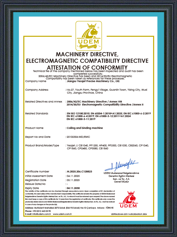
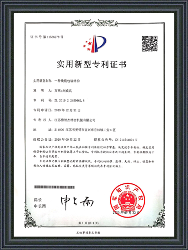
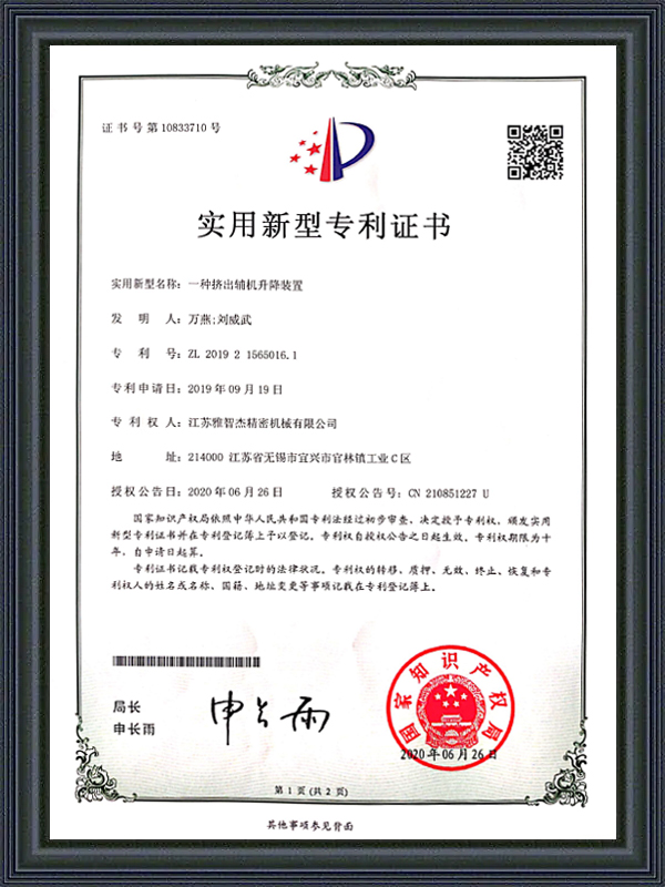
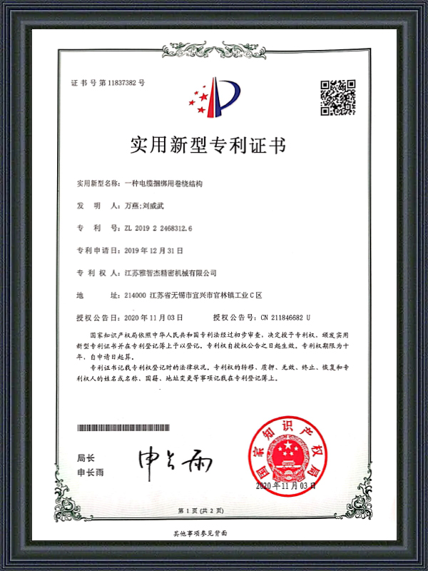
Honorary Certification
CERTIFICATE
Latest Updates
What'S News
-
Automatic Wire Winding Machine: How It Works & How to Choose the Right OneA single operator manually winding wire onto spools can process roughly 200–400 meters per hour. An automatic wire winding machine running at full speed handle...
-
Cable Insulation Extruder & Wire and Cable Extruder Machine: Full GuideBare copper goes in. Insulated, protected, ready-to-ship cable comes out. The machine that makes that transformation possible is the cable insulation extruder ...
-
Automatic Cable Labeling Machine: Cable Coil Labeling & Label Feeder GuideOn a cable production line running at full capacity, a single labeling station staffed by one operator can become the bottleneck that limits throughput across...
-
PP PVC PE Cable Extruder Machine: Multi-Material Guide for Cable ManufacturersSwitch a cable extrusion line from PVC to PP mid-run and two things will go wrong fast: barrel temperatures set for PVC's amorphous melt behavior will overshoo...
-
Automatic Cable Coiling and Wrapping Machine | PP Tape, Servo Motor GuideWhat Is an Automatic Cable Coiling and Wrapping Machine? An automatic cable coiling and wrapping machine combines two traditionally separate production steps —...
Industry Knowledge
Traversing Mechanism Design: How Wire Distribution Accuracy Affects Coil Quality
The traversing mechanism on a Coiling Machine governs how wire or cable is distributed laterally across the coil width during winding. In most production environments, traverse performance is evaluated by visual inspection of the finished coil face — but this surface check misses the most consequential quality issues, which develop inside the coil body over multiple layers. Uneven pitch distribution — caused by traverse speed mismatch with the winding speed, backlash in the traverse drive leadscrew, or inconsistent pitch programming at diameter transition points — creates localized pressure concentrations inside the coil where layers nest incorrectly. These pressure points distort the insulation geometry of the innermost cable layers and create conditions for abrasion damage during payout, particularly in applications where the cable is pulled from the center of the coil.
The engineering variable that directly controls traverse accuracy is the pitch-to-diameter ratio update rate. As a coil builds in diameter during winding, the linear surface speed at the winding point increases even if the mandrel RPM remains constant. A Coil Winding Machine that does not continuously recalculate and update the traverse pitch to compensate for this diameter growth will produce progressively tighter pitch at the inner layers and progressively wider pitch toward the outer layers — a defect that appears uniform on the coil face but produces a cross-section with non-parallel layer interfaces. Servo-driven traverse systems with real-time diameter compensation, derived either from a layer-count algorithm or from a direct diameter measurement sensor, eliminate this progressive pitch error across the full build height of the coil.
Shanghai Yessjet Precise Machinery Co., Ltd. implements servo-controlled traverse with closed-loop pitch compensation as standard on its Wire Cable Coiling Machine range. The traverse controller receives continuous feedback from the winding mandrel encoder and recalculates the pitch setpoint at every winding revolution, ensuring that the wire lay remains geometrically consistent from the first layer to the last regardless of coil build height or mandrel speed variation during acceleration and deceleration phases.
Dancer Roller Dynamics: Tuning Tension Control for Variable-Speed Winding
The dancer roller assembly on a Wire Coiling Machine performs a function that is more complex than it appears: it simultaneously buffers the speed difference between the upstream line and the coiling mandrel, measures wire tension through its displacement position, and provides the feedback signal that drives the tension control loop. When any one of these three functions is compromised — through incorrect dancer mass, worn pivot bearings, or a poorly tuned PID controller — the tension control system becomes either sluggish or oscillatory, producing coils with layer-to-layer tension variation that is invisible to visual inspection but detectable as conductor elongation variation when the cable is tested for resistance per unit length.
Dancer roller mass is the most frequently underspecified parameter in Cable Coiler installations. A dancer that is too light responds to high-frequency tension disturbances with excessive displacement excursion, saturating the control output and causing the tension loop to lose control during the coil changeover acceleration transient. A dancer that is too heavy has insufficient responsiveness to correct small tension deviations quickly, allowing them to accumulate across multiple coil layers. The correct dancer mass for a given application is determined by the wire's elastic modulus, the target tension setpoint, the maximum expected line speed variation rate, and the dancer arm geometry — a calculation that requires engineering analysis rather than rule-of-thumb estimation.
Dancer Roller Configuration Guide by Wire Type
| Wire/Cable Type | Recommended Dancer Mass | Control Priority | Primary Risk |
| Fine magnet wire (<0.5mm) | Ultra-light (50–150g) | Minimize tension overshoot | Wire break from tension spike |
| Medium building wire (1.5–6mm²) | Medium (0.5–2kg) | Balance response and stability | Layer tension variation, elongation |
| Heavy power cable (>16mm²) | Heavy (3–8kg) | Dampen high inertia transients | Coil collapse from tension loss |
| Flexible multi-core cable | Light-medium (200–800g) | Prevent jacket surface marking | Dancer contact marking on soft jacket |
Beyond mass selection, the PID tuning of the tension control loop requires separate parameter sets for low-speed and high-speed operating ranges. A single PID parameter set that stabilizes tension at 50 m/min will typically be under-damped at 300 m/min, producing visible oscillation in the dancer position that manifests as a rhythmic tension variation at the winding point. Gain-scheduled control — where the PID parameters are automatically adjusted as a function of line speed — is the technically correct solution and is available on modern servo drive platforms without requiring external controller hardware.
Mandrel Expansion Mechanics: Comparing Pneumatic and Servo-Electric Actuation
The expanding mandrel is the defining mechanical component of a modern Wire Cable Coiling Machine — it clamps the coil core during winding, maintains the target inner diameter throughout the winding cycle, and releases the finished coil cleanly for transfer to the downstream packaging station. Mandrel performance directly determines coil inner diameter consistency, transfer cycle time, and the rate of coil release failures that require manual intervention to clear. Despite its centrality to coiling performance, mandrel actuation technology has not been consistently modernized across the industry, and many machines still rely on pneumatic actuators whose limitations become significant at high production speeds.
Pneumatic mandrel actuation operates at a fixed air pressure that determines both the expansion force and the retraction speed. The key limitation is that pneumatic actuation force is not position-controlled — once the actuator reaches end-of-travel, the mandrel arms are held by air pressure alone, and any variation in supply pressure across the shift (common in facilities with shared compressed air systems) translates directly into variation in mandrel grip force. When grip force drops below the threshold needed to resist the winding tension at the outer coil layers, the mandrel slips rotationally, producing a layer displacement defect in the upper coil body that is difficult to detect until the coil is transferred and the defect becomes visible on the coil face.
Servo-electric mandrel actuation resolves this limitation by replacing the pneumatic cylinder with a servo motor and ballscrew or toggle mechanism that positions the mandrel arms to a precisely defined diameter and holds that position through motor torque rather than air pressure. The servo system provides real-time position feedback that confirms the mandrel is at the commanded diameter before the winding cycle begins, and maintains the commanded position throughout the winding cycle regardless of the reaction force from winding tension. Coil inner diameter repeatability on servo-actuated mandrels is typically ±0.5mm or better across a full production shift, compared to ±2–4mm on pneumatic systems under variable supply pressure conditions.
Cut-and-Transfer Sequence Optimization on High-Speed Cable Coilers
The cut-and-transfer sequence on a Cable Coiler — the coordinated series of events that ends one coil, cuts the cable, secures the tail, and positions the new coil core for winding — is the most time-critical phase of the entire coiling cycle. At line speeds of 300 m/min or above, the upstream cable production during a 3-second transfer sequence represents 15 meters of cable that must be accommodated in the accumulator buffer without causing a tension spike or a slack loop. Buffer capacity, cut timing, and transfer arm kinematics must be engineered as an integrated system rather than specified independently, because an underspecified buffer or a slow transfer sequence creates a constraint that limits the entire line's effective output speed regardless of the winding speed capability of the Cable Coiler itself.
The cut event itself requires precise synchronization between the cutter actuation signal and the cable position at the cutter blade. On rotary flying cutters — which cut the cable while both the cable and the cutter blade are in motion — the blade timing must account for the cable transport delay between the cutter position and the winding point. If the blade fires too early, the tail length on the finished coil is shorter than specified; if it fires too late, the lead length on the new coil extends past the first winding layer, creating a loose external tail that interferes with the strapping operation. The acceptable timing window for a clean cut at 300 m/min is typically less than 20 milliseconds, requiring a PLC with deterministic scan times rather than a general-purpose controller with variable cycle time.
- Buffer accumulator sizing: The minimum accumulator capacity must equal the cable output during the full transfer sequence time at maximum line speed — undersized accumulators force the upstream line to decelerate during every coil change, creating a cyclic speed disturbance that affects extrusion wall thickness consistency
- Tail securing method: Hot-air tail tucking is more reliable than mechanical tail clips for soft-jacketed cables at high speed because it does not require the tail to be presented at a precise position — the hot air stream deflects the tail regardless of its exact angle at the moment of cut
- Core pre-positioning: The new coil core should be loaded and confirmed in the standby mandrel position before the cut event, not after — any delay in core positioning after the cut extends the effective transfer time and increases the accumulator demand
- Transfer arm velocity profiling: The transfer arm should follow an S-curve velocity profile rather than a trapezoidal profile to minimize the jerk at the start and end of the transfer motion — high jerk values during coil transfer cause the finished coil to shift on the transfer arm, producing misaligned placement at the downstream strapping station
Preventive Maintenance Intervals for Wire Coiling Machine Mechanical Systems
Wire Coiling Machine mechanical systems operate under continuous cyclic loading that creates wear patterns distinct from those seen in most other types of industrial machinery. The mandrel expands and contracts on every coil cycle — potentially 300 to 500 times per shift on a high-speed building wire line — subjecting the mandrel pivot bearings and actuator mechanism to a cumulative cycle count that reaches millions of cycles within the first year of operation. Standard machinery maintenance intervals based on operating hours significantly underestimate the mechanical wear rate for these components, because the relevant degradation driver is cycle count rather than run time. A Wire Coiling Machine running at 400 m/min winding 50m coils accumulates 480 mandrel cycles per hour — eight times the cycle rate of a machine running the same hours but winding 400m coils.
Establishing maintenance intervals based on coil cycle count rather than operating hours requires the machine control system to log cumulative cycle counts for each wear-critical component and present maintenance alerts at the appropriate thresholds. This is a standard feature in modern Coil Winding Machine control platforms but is absent in older relay-logic or basic PLC-controlled machines, requiring operators to track cycle counts manually — a practice that is rarely maintained consistently in production environments. Where cycle-count tracking is not available in the control system, a conservative approach is to set time-based maintenance intervals at one-third of the supplier-recommended hours for high-cycle-count mechanical components.
Recommended Maintenance Intervals by Component and Trigger Basis
| Component | Maintenance Action | Cycle-Based Interval | Failure Mode if Neglected |
| Mandrel pivot bearings | Lubrication / replacement | Every 500,000 cycles | ID variation, mandrel arm seizure |
| Traverse leadscrew / belt | Backlash check / tension | Every 2,000 hours | Pitch error, layer misalignment |
| Dancer roller bearings | Friction check / replacement | Every 1,500 hours | Tension control instability |
| Cutter blade | Sharpness inspection / replacement | Every 200,000 cuts | Ragged cut, jacket burr, tail length error |
| Transfer arm guide rails | Wear measurement / lubrication | Every 3,000 hours | Coil misplacement, strapping station jam |
Founded in 2002 in Shanghai with investment from Taiwan, and expanded through Jiangsu Yessjet Precise Machinery Co., Ltd. in Yixing in 2017, Shanghai Yessjet Precise Machinery Co., Ltd. provides customers with a documented maintenance schedule specific to each Wire Coiling Machine configuration — not a generic equipment manual, but a maintenance plan calibrated to the actual coil cycle rate, product mix, and operating environment of the customer's facility. This schedule is delivered as part of the commissioning package and includes cycle-count thresholds for all wear-critical components, a recommended spare parts inventory sized for six months of planned maintenance, and a diagnostic checklist that operators can use to identify early-stage wear indicators before they develop into unplanned downtime events.
Quick Links
Product Categories
Contact Us
-
 [email protected]
-
 +86-0510-87258118
-
 +86-18888031330
-
 No. 27, Youth Farm, Fengyi Village, Guanlin Town, Yixing City, Jiangsu Province China.
Copyright © Shanghai Yessjet Precise Machinery Co., Ltd. Rights Reserved. Custom Wire Coiling Machine Factory
