

 LANGUAGE
 中文简体
中文简体 русский
 Français
 Español
 Português
 عربى
عربى


A single operator manually winding wire onto spools can process roughly 200–400 meters per hour. An automatic wire winding machine running at full speed handles that same volume in minutes — with zero variation in coil tension, zero misalignment, and no fatigue-related errors at the end of a shift....

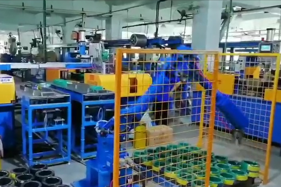
Intelligent Robot Stacker
Application: Can be used in handling, assembly, grinding, polishing, deburring and other scenes.
Beside cable packing industrial, it also Suitable for metal products, photovoltaic, warehousing logistics, food and beverage Other trades
Features:
1. It is easy to operate and control machinery by touching the human-machine interface, and easy to control mechanical stacking.
2. Reel the wire onto the stack.
3. The number of volumes per stack can be set by stacking system.
4. The length and width of the conveyor system can be customized according to customer requirements.
5. The automatic stacking system is divided into empty stacking area, working area and full load area.
6. When the automatic stack is finished, it will automatically detect and send a message to the operator.
- Technical Parameters
- Contact Us
Shanghai Yessjet Precise Machinery Co., Ltd.
Precision Machinery, Intelligent Solutions Powering Cable Production Worldwide
Shanghai Yessjet Precise Machinery Co., Ltd. was established in Shanghai with investment from
Taiwan
in 2002 as a professional manufacturer dedicated to the research and development of wire and cable
machinery.
In 2017, to expand the company's scale, Jiangsu Yessjet Precise Machinery Co., Ltd. was established with
investment
in Yixing, Wuxi, Jiangsu.
We specialize in designing and manufacturing high-performance production systems — from extrusion lines and automatic coiling machines to robotic palletizing solutions — helping customers achieve efficiency, flexibility, and sustainable growth. As Robotic Palletizer Manufacturers and Intelligent Robot Stacker Suppliers, we provide professional on-site installation and system commissioning services to ensure rapid equipment startup and stable operation. We also conduct operator training to guarantee efficient production line launch. Custom Intelligent Stacking Robot Arm. For existing production lines, we offer customized retrofit solutions. Through partial upgrades or automated integration, we help clients enhance production capacity, precision, and intelligent capabilities to maximize return on investment.
View
More
We specialize in designing and manufacturing high-performance production systems — from extrusion lines and automatic coiling machines to robotic palletizing solutions — helping customers achieve efficiency, flexibility, and sustainable growth. As Robotic Palletizer Manufacturers and Intelligent Robot Stacker Suppliers, we provide professional on-site installation and system commissioning services to ensure rapid equipment startup and stable operation. We also conduct operator training to guarantee efficient production line launch. Custom Intelligent Stacking Robot Arm. For existing production lines, we offer customized retrofit solutions. Through partial upgrades or automated integration, we help clients enhance production capacity, precision, and intelligent capabilities to maximize return on investment.
YESSJET
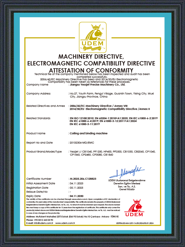
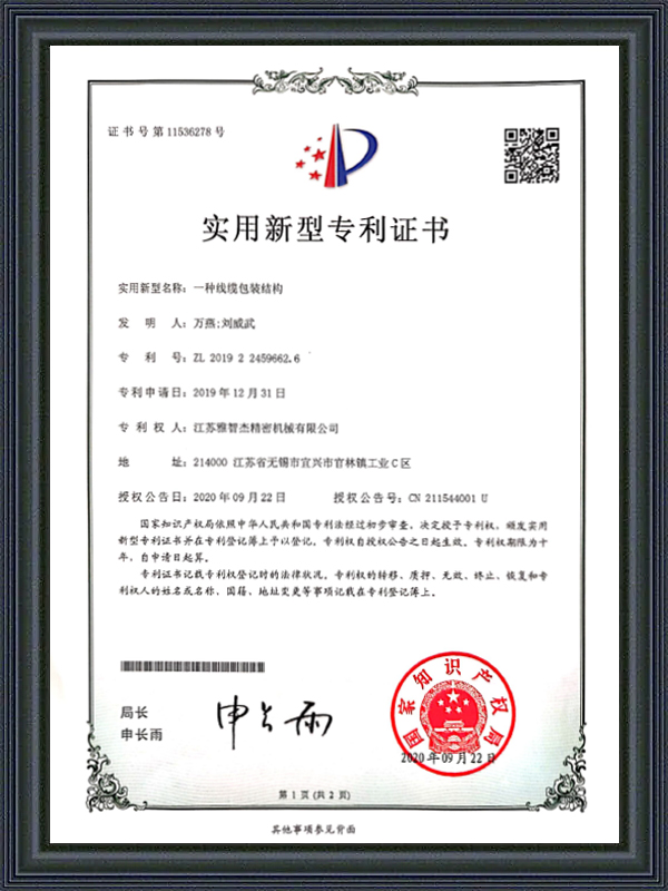
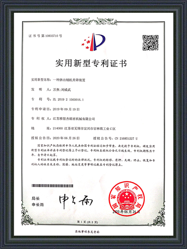
Honorary Certification
CERTIFICATE
Latest Updates
What'S News
-
Automatic Wire Winding Machine: How It Works & How to Choose the Right One
-
Cable Insulation Extruder & Wire and Cable Extruder Machine: Full GuideBare copper goes in. Insulated, protected, ready-to-ship cable comes out. The machine that makes that transformation possible is the cable insulation extruder — and choosing the right one shapes every metre of cable your factory will ever produce. This guide covers how these machines work, what the...
-
Automatic Cable Labeling Machine: Cable Coil Labeling & Label Feeder GuideOn a cable production line running at full capacity, a single labeling station staffed by one operator can become the bottleneck that limits throughput across the entire packaging sequence. Manual cable coil labeling is slow, inconsistent, and—when the operator is fatigued or distracted—prone to c...
Industry Knowledge
End-of-Arm Tooling Selection for Robotic Palletizer Systems Handling Coiled Cable
The end-of-arm tool (EOAT) on a Robotic Palletizer is the single component most responsible for whether the system actually meets its cycle time and placement accuracy targets in production — yet it receives far less engineering attention than the robot arm itself during the specification phase. For cable manufacturers, the challenge is particularly acute because coiled cable is a mechanically awkward payload: it is round, relatively deformable, variable in outer diameter across product families, and often presented at inconsistent positions and orientations on the infeed conveyor. A gripper designed for rigid cartons or uniform bags will fail repeatedly on coiled cable, producing placement errors that accumulate into unstable pallet loads and require manual intervention to correct.
The two dominant EOAT approaches for coiled cable palletizing are clamp grippers and fork-style lifters. Clamp grippers apply lateral pressure from two or more jaw faces to hold the coil during transfer — effective for coils with a consistent outer diameter and a jacket material stiff enough to resist deformation under clamping force. Fork-style lifters insert two or more tines beneath the coil and lift from below, which is inherently more forgiving of OD variation but requires the coil to be presented at a known height above the conveyor surface and demands sufficient clearance beneath the coil for tine insertion. For mixed-product environments running cable ODs from 8mm to 60mm on the same palletizing cell, a hybrid tool with adjustable clamp width and a retractable bottom support offers the widest compatibility range at the cost of higher tooling complexity and longer changeover time between product families.
Shanghai Yessjet Precise Machinery Co., Ltd. develops EOAT specifications as part of the Intelligent Robot Stacker system design process, beginning with a payload matrix that documents coil OD range, coil weight range, jacket material hardness, and strapping configuration for every cable product the customer intends to run. This matrix drives both the tool mechanical design and the robot program trajectory, because a heavier coil or a larger OD requires a different approach angle and deceleration profile to maintain placement accuracy within the ±5mm tolerance that most pallet patterns require for stable stacking.
Pallet Pattern Programming: Static Patterns vs. Adaptive Layer Logic
Pallet pattern programming in an Intelligent Stacking Robot Arm system is more complex for round coiled products than for rectangular cartons, because circles do not tessellate efficiently and the gap management between coils determines both pallet stability and the effective payload density per pallet. Static pattern programming — where every layer follows a pre-defined coil placement grid — is straightforward to implement and produces predictable results for a single product. However, static patterns become a liability in mixed-product environments where coil OD varies across runs, because a pattern optimized for a 200mm OD coil will leave excessive gaps or cause coil-to-coil contact interference when the line switches to a 240mm OD product without pattern adjustment.
Adaptive layer logic addresses this by calculating the placement grid at runtime based on the actual coil OD measured by the vision system or entered via the recipe management interface. The robot controller determines how many coils fit per layer at the current OD, calculates the optimal row and column spacing to center the pattern within the pallet footprint, and generates the waypoints for each placement move dynamically. This approach eliminates the need to maintain a library of static patterns for every product SKU — a library that in practice grows unwieldy and becomes a maintenance burden as new cable products are introduced.
Comparison of Pattern Approaches by Production Environment
| Pattern Type | Best For | Key Limitation | Changeover Time |
| Static pre-programmed | Single product, high-volume dedicated lines | Requires new program per SKU; pattern library grows unmanageable | 2–5 min (recipe select) |
| OD-adaptive calculated | Mixed OD environments, frequent product changes | Requires accurate OD input; edge-of-pallet placement needs boundary check | Under 1 min (parameter entry) |
| Vision-guided dynamic | High-mix, variable coil presentation positions | Higher system cost; vision calibration requires periodic maintenance | Near-zero (automatic detection) |
Layer interlock patterns — where alternate layers are rotated 90 degrees or offset by half a coil pitch — improve pallet stability significantly for round coils, which have no flat face to prevent lateral sliding. Implementing layer interlock in an adaptive pattern system requires the robot controller to track the current layer number and apply the correct rotation offset to the calculated grid, a logic step that is straightforward to implement but is often omitted in basic static-pattern systems because it requires more complex pattern programming than operators are typically trained to perform.
Cycle Time Analysis: Where Intelligent Robot Stacker Systems Lose Time in Real Production
Supplier-quoted cycle times for an Intelligent Robot Stacker are almost always measured under ideal conditions: one coil size, pre-positioned at a fixed infeed point, placed on an empty pallet at a fixed height, with no pallet changeover events. Real production cycle times are consistently 15–30% longer than these quoted figures because of factors that are present in every production shift but absent from the benchmark test: coil position variation on the infeed conveyor, pallet height growth as layers accumulate, pallet exchange downtime, and the occasional re-pick when a coil is not seated correctly on the first placement attempt.
The largest recoverable time loss in most Intelligent Stacking Robot Arm installations is the pallet exchange sequence — the time between the robot placing the last coil on a full pallet and the first placement on a new empty pallet. Manual pallet exchange using a forklift typically takes 60–120 seconds; during this window the upstream coiling line either stops or accumulates coils on a buffer conveyor that may not have sufficient capacity for a long exchange sequence. Automated pallet dispensers — which pre-position an empty pallet beneath the robot work envelope while the current pallet is still being filled — reduce the exchange gap to 10–20 seconds and eliminate the dependency on forklift availability, which in multi-line facilities is frequently a shared resource that creates scheduling conflicts.
- Infeed conveyor positioning: Coil position variation of ±30mm on the infeed conveyor adds 0.3–0.8 seconds per pick cycle for a vision-guided system performing position correction — across 500 picks per shift, this represents 2.5–6.5 minutes of cumulative lost time
- Pallet height compensation: Each successive layer raises the placement point by the coil stack height; the robot must travel a longer vertical distance for upper layers, adding 0.2–0.5 seconds per placement compared to the ground-layer cycle — this effect compounds across a full pallet of 6–8 layers
- Re-pick events: Coils that are not seated correctly after the first placement attempt require the robot to lift, reposition, and re-place — a sequence that takes 3–8 seconds and occurs at a rate of 1–3% of total picks in systems without placement confirmation sensors
- Strapping tail interference: Loose strap tails on imperfectly strapped coils can interfere with adjacent coils during placement, requiring a 2–5 second dwell for the tail to settle before the robot releases the coil — a problem that traces back to the upstream strapping station rather than the robot itself
Vision System Integration in Robotic Palletizer Cells: Calibration and Drift Management
Vision-guided Robotic Palletizer systems in cable manufacturing environments face calibration challenges that differ from typical industrial vision applications because the working environment combines vibration from adjacent machinery, variable ambient lighting from overhead crane movement, and product surface characteristics — strapped coils with reflective strap material and matte or semi-gloss jacket finishes — that create inconsistent image contrast depending on lighting angle and jacket color. A vision system calibrated in the morning under stable factory lighting may produce pick position errors of 5–15mm by mid-shift if overhead crane shadows or adjacent equipment vibration have shifted the effective image centroid calculation.
The most effective approach to managing vision calibration drift in production environments is a combination of fixed structured lighting within the vision field-of-view — independent of ambient factory lighting — and a periodic in-cycle calibration verification routine. The structured lighting, typically a ring light or linear bar light mounted on the camera bracket, ensures that the illumination geometry is constant regardless of ambient conditions. The in-cycle calibration check involves the robot periodically picking a reference target at a known position and comparing the vision system's reported position to the known ground truth; deviations above a threshold trigger an automatic recalibration routine before production continues.
Thermal drift is a secondary calibration concern in facilities without climate control. The camera mounting bracket and robot base both expand thermally during the day, shifting the spatial relationship between the camera frame and the robot world frame by fractions of a millimeter that accumulate into placement errors of 3–8mm by peak afternoon temperature. Compensating for thermal drift requires either a temperature-coefficient correction in the robot-to-camera transformation matrix — derived from a calibration run at multiple temperatures — or a rigid Invar-alloy mounting structure for the camera that minimizes thermal expansion. Most production facilities address this pragmatically by widening the placement tolerance in the pallet pattern to absorb the drift range, accepting a slight reduction in pallet density in exchange for elimination of the calibration maintenance burden.
Safety Architecture in Intelligent Stacking Robot Arm Cells: Beyond the Safety Fence
Traditional safety architecture for industrial robot cells relies on a physical perimeter fence with interlocked access gates — a solution that is effective but creates operational friction in facilities where operators need frequent access to the robot work envelope for coil jam clearing, pallet quality inspection, or strap tail management. In high-throughput cable palletizing operations, frequent fence interruptions reduce effective system uptime significantly because each gate entry triggers a full safety stop and requires a deliberate restart sequence before production resumes. The cumulative effect across a production shift can account for 5–10% of total available time, offsetting a portion of the labor savings the Intelligent Stacking Robot Arm was installed to deliver.
Modern Intelligent Robot Stacker installations increasingly use collaborative safety architectures that replace or supplement the perimeter fence with area scanners, safety-rated vision systems, and force-limited robot modes. Area scanners — laser-based safety devices mounted at floor level — define configurable safety zones within the robot work envelope. When an operator enters a defined zone, the robot reduces to a safe reduced speed (typically 250mm/s or below, per ISO/TS 15066) rather than stopping completely, allowing limited human-robot coexistence for inspection and minor intervention tasks without a full production halt. Full stop is still triggered if the operator penetrates the inner exclusion zone around the active pick-and-place area.
- Safety-rated monitored stop (SRMS): The robot stops and holds position when an operator enters the monitored zone; production resumes automatically when the operator exits — no manual restart required, reducing the access-event downtime to the transit time through the zone
- Speed and separation monitoring (SSM): The robot continuously reduces speed as the operator approaches, calculated in real time from the scanner distance measurement — the closest approach distance determines whether the robot decelerates to slow speed, reduced speed, or protective stop
- Power and force limiting (PFL): Available on collaborative robot platforms, PFL limits the force the robot arm can exert on contact — suitable for lower-payload cable coil applications where the coil weight is within the collaborative robot payload range (typically up to 16kg for current collaborative platforms)
- Safety PLC integration: All safety functions — area scanner zones, gate interlocks, emergency stop circuits, and robot safety inputs — should be managed through a dedicated safety PLC (SIL 2 or PLe rated) rather than through the standard machine PLC, ensuring that safety logic cannot be inadvertently modified during recipe or program changes
Founded in 2002 in Shanghai and expanded through the establishment of Jiangsu Yessjet Precise Machinery Co., Ltd. in Yixing in 2017, Shanghai Yessjet Precise Machinery Co., Ltd. designs Robotic Palletizer safety architectures in compliance with ISO 10218-2 and GB 11291.2 requirements from the initial system layout phase. Safety zone configuration, access frequency analysis, and restart procedure design are documented during the factory acceptance test and validated on-site during commissioning — ensuring that the safety architecture as installed matches the actual operator workflow in the customer's facility rather than a theoretical access pattern assumed during the design phase.
Quick Links
Product Categories
Contact Us
-
 [email protected]
-
 +86-0510-87258118
-
 +86-18888031330
-
 No. 27, Youth Farm, Fengyi Village, Guanlin Town, Yixing City, Jiangsu Province China.
Copyright © Shanghai Yessjet Precise Machinery Co., Ltd. Rights Reserved. Custom Intelligent Robotic Palletizer Manufacturers
