

 LANGUAGE
 中文简体
中文简体 русский
 Français
 Español
 Português
 عربى
عربى


Motorized Pay-Off Equipment Machine
The machine can automatically pay-of or take-up wires and cables into coil.
Wide range of application: Suitable for various wires and cables, suitable for laying wires such as BV, BVR, RVV, UL electronic wires, flower wires and other wire types.
These functions make the rocking plate coating machine have the advantages of high efficiency, automation and labor saving in the production of wires and cables, and can significantly improve production efficiency and product quality.
Features:
1. Type: Shaft-less type, drum loaded by cantilever arms with hydraulic lifters both side. Drum lock/release done by motors or hand screw.
2. Motorized cable-sending unit is available, machine completed with bobin drivern system.
3. Application: for cable pay of in the process of cable manufacturing or rewinding.
The motorized pay-off equipment machine is a core industrial device designed for stable, controlled unwinding of coiled materials including wires, cables, and metal strips. It integrates a variable-frequency drive motor to adjust unwinding speed precisely, matching the pace of downstream processing such as cutting, extrusion, and weaving, thus eliminating material tension fluctuations and preventing tangling or stretching damage.
Equipped with a tension control system and automatic alignment mechanism, the machine maintains consistent material tension and ensures neat unwinding even with heavy coils. Its robust frame accommodates different coil weights and sizes, while safety features like overload protection and emergency stop buttons safeguard operators and equipment during continuous operation.
Widely applied in wire and cable manufacturing, wire harness processing, and metalworking industries, this machine improves production efficiency, reduces material waste, and ensures stable product quality, serving as a reliable auxiliary device for automated production lines.
- Technical Parameters
- Contact Us


Shanghai Yessjet Precise Machinery Co., Ltd.
Precision Machinery, Intelligent Solutions Powering Cable Production Worldwide
Shanghai Yessjet Precise Machinery Co., Ltd. was established in Shanghai with investment from
Taiwan
in 2002 as a professional manufacturer dedicated to the research and development of wire and cable
machinery.
In 2017, to expand the company's scale, Jiangsu Yessjet Precise Machinery Co., Ltd. was established with
investment
in Yixing, Wuxi, Jiangsu.
We specialize in designing and manufacturing high-performance production systems — from extrusion lines and automatic coiling machines to robotic palletizing solutions — helping customers achieve efficiency, flexibility, and sustainable growth. As Automatic Motorized Wire Cable Pay-Off Equipment Suppliers and Motorized Cable Pay-Off Machine Factory, we provide professional on-site installation and system commissioning services to ensure rapid equipment startup and stable operation. We also conduct operator training to guarantee efficient production line launch. Custom Automatic Wire Cable Pay-Off Machine Manufacturer. For existing production lines, we offer customized retrofit solutions. Through partial upgrades or automated integration, we help clients enhance production capacity, precision, and intelligent capabilities to maximize return on investment.
View
More
We specialize in designing and manufacturing high-performance production systems — from extrusion lines and automatic coiling machines to robotic palletizing solutions — helping customers achieve efficiency, flexibility, and sustainable growth. As Automatic Motorized Wire Cable Pay-Off Equipment Suppliers and Motorized Cable Pay-Off Machine Factory, we provide professional on-site installation and system commissioning services to ensure rapid equipment startup and stable operation. We also conduct operator training to guarantee efficient production line launch. Custom Automatic Wire Cable Pay-Off Machine Manufacturer. For existing production lines, we offer customized retrofit solutions. Through partial upgrades or automated integration, we help clients enhance production capacity, precision, and intelligent capabilities to maximize return on investment.
YESSJET
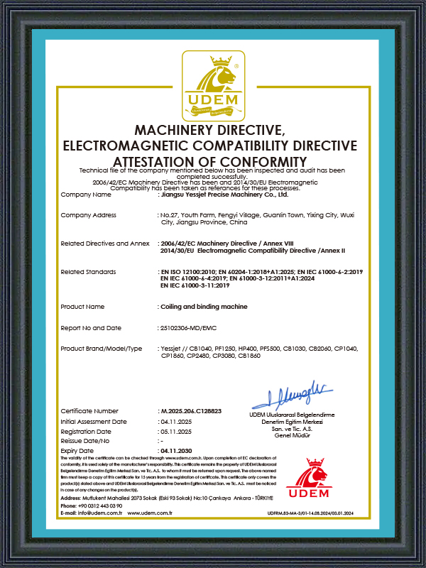
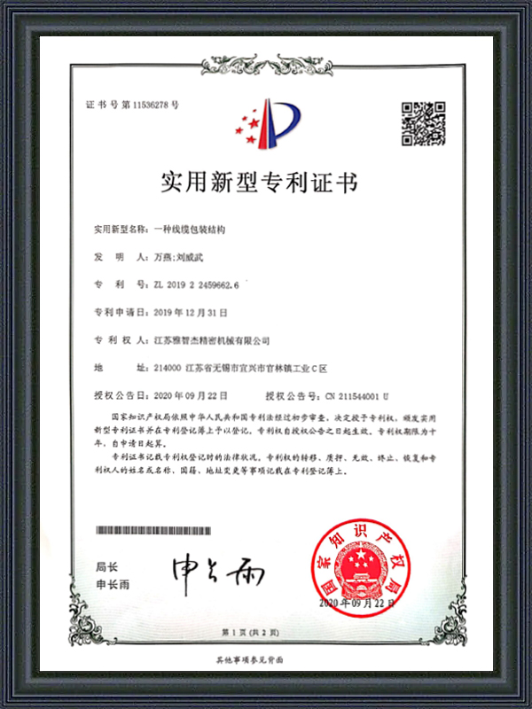
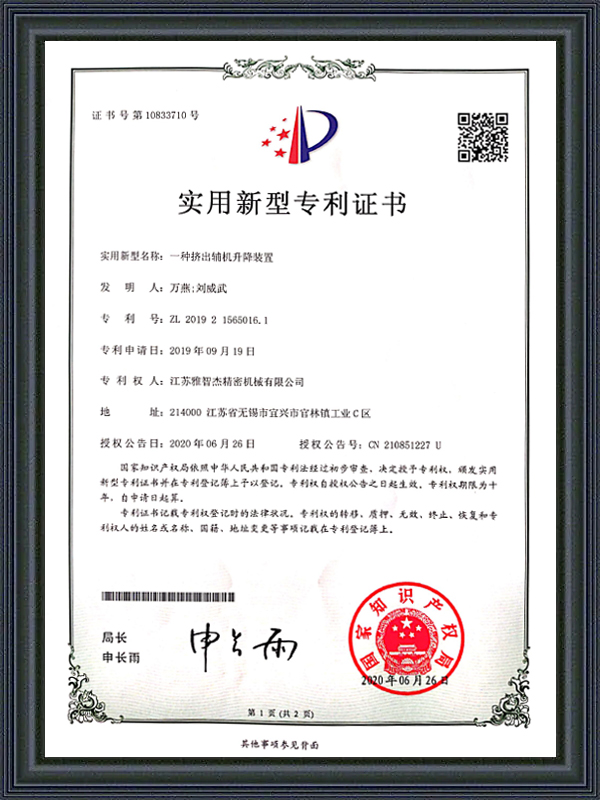
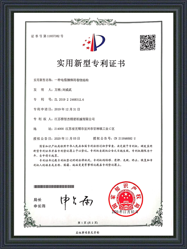
Honorary Certification
CERTIFICATE

Latest Updates
What'S News
-
Automatic Wire Winding Machine: How It Works & How to Choose the Right OneA single operator manually winding wire onto spools can process roughly 200–400 meters per hour. An automatic wire winding machine running at full speed handles that same volume in minutes — with zero variation in coil tension, zero misalignment, and no fatigue-related errors at the end of a shift....
-
Cable Insulation Extruder & Wire and Cable Extruder Machine: Full GuideBare copper goes in. Insulated, protected, ready-to-ship cable comes out. The machine that makes that transformation possible is the cable insulation extruder — and choosing the right one shapes every metre of cable your factory will ever produce. This guide covers how these machines work, what the...
-
Automatic Cable Labeling Machine: Cable Coil Labeling & Label Feeder GuideOn a cable production line running at full capacity, a single labeling station staffed by one operator can become the bottleneck that limits throughput across the entire packaging sequence. Manual cable coil labeling is slow, inconsistent, and—when the operator is fatigued or distracted—prone to c...
Industry Knowledge
Active Tension Control in Motorized Wire Cable Pay-Off Equipment: How It Differs from Passive Braking
The fundamental distinction between motorized and passive pay-off systems lies in how back-tension is generated and maintained during the unwinding process. Passive systems — magnetic powder brakes, friction disc brakes, or mechanical drag mechanisms — apply a fixed or manually adjustable resistance torque to the spool shaft, relying on the mechanical drag to create tension in the wire as it is pulled by the downstream process. This approach works adequately in steady-state conditions but fails predictably at the two most critical moments of any production run: acceleration from standstill and deceleration to stop. During acceleration, the inertia of a full heavy cable spool means the brake torque required to maintain target tension is significantly higher than during steady-state running — a passive brake set for steady-state tension will allow a slack loop to form during acceleration, which then snaps taut as the downstream speed stabilizes and creates a tension spike that can elongate fine conductors or break wires entirely.
Motorized Wire Cable Pay-Off Equipment resolves this by actively driving the spool in the unwind direction with a controlled torque that offsets the spool inertia during acceleration and deceleration phases. The drive system — typically a vector-controlled AC motor or a servo drive — receives a speed reference from the downstream line and applies a torque command calculated to maintain the dancer roller at its target position throughout the full speed range. When the downstream line accelerates, the motorized pay-off drive increases its output torque to unwind cable proactively rather than waiting for the dancer to drop and signal a tension deficit. The result is a tension profile that remains within ±5% of setpoint across the entire acceleration and deceleration envelope — a level of control that passive systems cannot achieve on large-diameter, high-inertia cable spools.
Shanghai Yessjet Precise Machinery Co., Ltd. integrates inertia compensation algorithms into the drive configuration of its Motorized Wire Cable Pay-Off Equipment, calibrated to the actual spool diameter and weight range specified for each installation. The inertia compensation parameters are set during commissioning using a controlled acceleration ramp test, and the resulting tension stability is verified against the target envelope before the line enters production — ensuring that the performance characteristics meet process requirements from the first production run rather than requiring extended trial-and-error tuning by the customer's operators.
Spool Diameter Compensation: Why Pay-Off Tension Drifts Without It
A cable spool being unwound on a Motorized Cable Pay-Off Machine changes its effective diameter continuously throughout the run — starting at the outer layer diameter and decreasing to the core diameter as the cable is consumed. For a typical large industrial spool, this diameter change can represent a 3:1 to 5:1 ratio between the full and empty states. If the pay-off drive maintains a constant rotational speed setpoint rather than compensating for this diameter change, the linear cable output speed will decrease proportionally as the spool empties, forcing the downstream process to either accept variable feed speed or rely on the accumulator buffer to absorb the deficit. On extrusion lines where conductor feed speed directly affects insulation wall thickness, uncompensated diameter change in the pay-off translates into a progressive wall thickness increase as the spool empties — a defect that develops slowly enough to pass initial quality checks but fails on statistical sampling across the reel length.
The correct engineering approach is continuous spool diameter estimation with automatic speed correction applied to the pay-off drive. Diameter estimation can be implemented through three methods, each with different accuracy characteristics and hardware requirements:
- Dancer position integration: The dancer roller displacement is integrated over time to estimate consumed cable length, which is combined with the known spool geometry to calculate the current winding diameter — effective for consistent spool geometries but accumulates error if the dancer is operated near its travel limits for extended periods
- Speed ratio calculation: The ratio between the pay-off spool encoder speed and the downstream line encoder speed is used to calculate the effective unwinding diameter in real time — accurate and self-correcting but requires a reliable speed signal from the downstream process that is synchronized to the pay-off controller
- Direct optical measurement: A laser distance sensor or ultrasonic transducer measures the current spool outer diameter directly — the highest accuracy method, independent of accumulated calculation error, but adds sensor hardware cost and requires protection from cable dust and lubricant contamination in the measurement field
In practice, the speed ratio calculation method offers the best balance of accuracy and implementation simplicity for most Automatic Wire Cable Pay-Off Machine installations. The compensation update rate should be sufficient to track diameter changes between individual winding layers — for a typical cable at 1.5mm insulated diameter on a 400mm traverse-width spool, each layer represents approximately 0.003mm of diameter change, requiring an update rate of at least one calculation per spool revolution to maintain compensation accuracy within 0.5% of actual diameter.
Spool Loading and Alignment: The Mechanical Factors That Determine Tension Uniformity
Tension non-uniformity in Motorized Wire Cable Pay-Off Equipment is frequently attributed to control system issues when the actual root cause is mechanical misalignment at the spool mounting point. A spool mounted with its rotational axis non-perpendicular to the pay-off direction — even by 1 to 2 degrees — creates a sinusoidal tension variation at the winding frequency as the cable pulls alternately toward and away from the flange face during unwinding. This tension ripple appears on the dancer roller as a rhythmic oscillation that the tension control loop cannot suppress because the disturbance frequency matches or exceeds the control loop bandwidth. The resulting tension variation is typically 8–15% peak-to-peak at the winding frequency and does not respond to PID tuning adjustments, leading operators to incorrectly conclude that the control system is the source of the problem.
Proper spool alignment requires both axial perpendicularity and lateral centering of the spool relative to the pay-off direction. Axial perpendicularity is set by the pay-off frame geometry and the spool shaft bearing block alignment — verified using a dial indicator traversed along the spool flange face while the shaft is rotated by hand. Lateral centering ensures that the cable exits the spool at the correct angle for the first guide eyelet, minimizing the fleet angle — the angle between the cable exit point at the spool and the center line of the first guide — which should be kept below 1.5 degrees to prevent flange wear and edge abrasion on the outermost cable layers.
Common Spool Mounting Errors and Their Tension Effects
| Mounting Error | Tension Symptom | Detection Method | Correction |
| Axial non-perpendicularity (>1.5°) | Sinusoidal tension ripple at winding frequency | Dial indicator on flange face during rotation | Shim bearing block, realign shaft |
| Lateral offset (>±5mm) | Flange edge abrasion, progressive tension increase | Fleet angle measurement at first guide | Lateral position adjustment of spool carriage |
| Spool bore-to-shaft clearance excess | Random tension spikes, spool wobble | Runout measurement at spool OD | Replace spool or fit reducing adapter sleeve |
| Unbalanced spool (damaged flange) | Tension ripple at 1× and 2× rotational frequency | Visual inspection, vibration measurement | Replace spool; do not attempt to balance in field |
Reel Change Sequence Design: Minimizing Downtime Without Compromising Tension Control
The reel change event — transitioning from a depleted spool to a new full spool on an Automatic Wire Cable Pay-Off Machine — is the highest-risk moment in the pay-off system's operating cycle from both a production continuity and a tension control perspective. On lines without a dedicated reel change accumulator, the downstream process must stop completely for the duration of the change sequence, which on a manually loaded system typically takes 3 to 8 minutes depending on spool weight and handling equipment availability. For an extrusion line running continuously, even a 3-minute stop requires a startup purge and stabilization period before product quality returns to specification — effectively making the total production loss per reel change 8 to 15 minutes of usable output.
Flying splice systems — which join the tail of the depleted spool to the lead of the new spool while both are in motion — eliminate this production loss but require precise timing coordination between the splice actuator, the pay-off drive, and the accumulator system. The splice must occur while the accumulator is releasing its stored cable length to maintain downstream line speed during the momentary stop of the depleted spool. If the accumulator capacity is insufficient to cover the full splice sequence time, the downstream process will experience a tension dropout that causes the extrusion crosshead to see a momentary tension reduction — potentially allowing the conductor to wander off-center within the die and producing a length of eccentric insulation that must be scrapped.
- Accumulator sizing for flying splice: The accumulator stroke length must store at least 1.5 times the cable output during the maximum expected splice sequence time, with the additional 50% margin accounting for variation in operator response time and splice head cycle time under production conditions
- Tail-end detection reliability: Optical or inductive sensors that detect the spool near-empty condition must trigger the splice initiation signal with sufficient advance notice — typically when 2 to 3 layers of cable remain on the spool — to allow the accumulator to build its full storage capacity before the splice event begins
- New spool pre-acceleration: The new spool drive should accelerate the fresh spool to match the current line surface speed before the splice clamp engages — splicing to a stationary or slow-moving spool creates a tension impulse as the splice point transitions from the old spool to the new one, potentially breaking the splice joint on fine-gauge wire
- Post-splice tension re-stabilization: After the splice, the pay-off tension control loop requires a re-stabilization period as it transitions from operating on the old spool inertia characteristics to the new full spool — the control system should apply a soft transition in the inertia compensation parameters rather than an immediate step change to prevent overshoot
Integration of Motorized Cable Pay-Off Machine with Extrusion Line Control Systems
A Motorized Cable Pay-Off Machine operating as a standalone unit — with its own independent tension setpoint and dancer control loop — introduces an inherent conflict with the extrusion line's haul-off speed control system. Both systems are attempting to regulate the cable tension at their respective points: the pay-off maintains upstream tension at the conductor entry, and the haul-off maintains downstream tension at the insulated cable exit. If these two control loops are not coordinated through a shared communication link, they can enter a conflicting oscillation where the pay-off increases tension in response to a dancer drop while the haul-off simultaneously reduces speed in response to a tension increase — creating a sustained back-and-forth interaction that neither loop can resolve independently.
The correct integration approach is a hierarchical control architecture where the extrusion line master PLC provides a speed reference to the Motorized Wire Cable Pay-Off Equipment drive as a feedforward signal, with the pay-off dancer position control loop acting as a trim adjustment on top of the master speed reference rather than as an independent speed controller. In this configuration, the pay-off drive follows the line speed proactively through the feedforward signal, and the dancer loop only needs to correct for residual speed mismatches — reducing the control bandwidth requirement and eliminating the potential for loop interaction. The communication link between the line master PLC and the pay-off drive should use a deterministic fieldbus protocol — PROFIBUS, EtherNet/IP, or PROFINET — with a cycle time below 10 milliseconds to ensure the feedforward signal is delivered with sufficient timeliness to be effective during line acceleration ramps.
Established in Shanghai in 2002 and expanded through Jiangsu Yessjet Precise Machinery Co., Ltd. in Yixing in 2017, Shanghai Yessjet Precise Machinery Co., Ltd. designs Motorized Wire Cable Pay-Off Equipment with native integration capability for the extrusion line control platforms most commonly used in cable manufacturing — including Siemens S7 series, Mitsubishi Q and iQ-R series, and Allen-Bradley ControlLogix. The pay-off drive interface is pre-configured to accept a master speed reference via the appropriate fieldbus protocol, with the dancer trim loop parameters factory-set to a stable starting configuration that operators can fine-tune on-site without requiring drive programming expertise. This integration approach reduces commissioning time for new line installations and eliminates the control interaction problems that are common when pay-off equipment from different suppliers is added to an existing extrusion line without engineering coordination of the control architecture.
Tension Setpoint Selection for Different Conductor Materials and Gauges
Selecting the correct tension setpoint on an Automatic Wire Cable Pay-Off Machine is not a matter of choosing a comfortable middle value within the machine's operating range — it is a material-specific calculation that balances three competing requirements: sufficient tension to maintain conductor straightness and prevent spool unwind snarls, low enough tension to avoid conductor elongation beyond the elastic limit, and a stable enough tension to prevent conductor wander within the extrusion die. Each of these requirements imposes a different constraint on the acceptable tension window, and the intersection of all three constraints defines the correct operating range for a given conductor specification.
Conductor elongation is the most critical constraint for fine-gauge and high-purity conductors. When pay-off tension exceeds the conductor's proportional limit — the stress level below which deformation is fully elastic — permanent elongation occurs, reducing the conductor cross-sectional area and increasing its resistance per unit length. For oxygen-free copper (OFC) conductors, the proportional limit is lower than for standard electrolytic tough pitch (ETP) copper, meaning that tension setpoints acceptable for standard wire may cause measurable elongation on OFC conductors of the same gauge. The tension limit in Newtons for a given conductor can be calculated from the proportional stress limit (typically 30–40% of yield strength for a conservative operating margin) multiplied by the conductor cross-sectional area — a calculation that should be performed for every conductor specification rather than assumed to scale linearly with conductor weight.
| Conductor Type | Cross Section | Max Recommended Pay-Off Tension | Primary Constraint |
| ETP Copper solid | 1.5 mm² | 18–22 N | Straightness / die centering |
| ETP Copper solid | 6 mm² | 55–70 N | Straightness / snarl prevention |
| OFC Copper stranded | 2.5 mm² | 20–28 N | Elongation limit (lower yield) |
| Aluminum solid | 10 mm² | 40–55 N | Low elongation margin vs. copper |
| Steel-core ACSR | 16 mm² | 120–160 N | Spool unwind snarl prevention |
These values serve as engineering starting points and must be verified against the specific conductor supplier's mechanical property data for the actual production lot. Conductor mechanical properties vary between suppliers and between production batches from the same supplier — particularly for stranded conductors where the individual wire drawing parameters affect the final strand yield strength. Establishing a tension validation protocol — including a short test run at the proposed setpoint followed by resistance-per-meter measurement on a sample length — provides confirmation that the operating tension is within the elastic range for the actual material being processed, rather than relying solely on nominal material specifications.
Quick Links
Product Categories
Contact Us
-
 [email protected]
-
 +86-0510-87258118
-
 +86-18888031330
-
 No. 27, Youth Farm, Fengyi Village, Guanlin Town, Yixing City, Jiangsu Province China.
Copyright © Shanghai Yessjet Precise Machinery Co., Ltd. Rights Reserved. Motorized Wire Cable Pay-Off Equipment Suppliers
