LANGUAGE
 中文简体
 русский
 Français
 Español
 Português
 عربى

Content
- 1 Design the Wall Before You Design the Die
- 2 Die Geometry, Land Length and Drawdown Decide the Rest
- 3 Tolerance Data You Can Actually Quote
- 4 Hidden Cost Drivers in Tooling Decisions
- 5 How Tooling Priorities Shift by Application
- 6 A Six-Step Tooling Development Sequence
- 7 Cooling, Sizing and Non-Stop Take-Off
- 8 Maintenance, Changeover and Compliance Practices
A 90 mm rigid PVC window profile that gauges within 0.05 mm on the bench can still fail at the customer's assembly line, because the die was cut to nominal geometry instead of shrink-compensated geometry. That single decision separates a line that cruises at 12 m/min from one that fights the operator at 7 m/min for six months after installation.
The short answer first: most plastic extrusion tooling problems are settled on paper, not on the machine. Wall uniformity, land length, drawdown balance and the tolerance callouts on the drawing account for the majority of dies that never stabilize. Handle those four properly and cutting the steel becomes routine machining work; get them wrong and no amount of screw speed or barrel zone tuning will recover the profile.
The four guidelines that carry the most weight
- Keep the thickest-to-thinnest wall ratio inside 2:1 for unfilled polymers and 1.5:1 for high-shrink semicrystalline grades.
- Set land length at 6–10 times the die gap for rigid PVC and 10–20 times for polyolefins, then balance every land so each wall sees similar shear.
- Design drawdown ratio between 1.5 and 3.0 for profiles, with wall-to-wall drawdown balance held at 1.0–1.2.
- Quote tolerances the process can actually hold, not the tolerances an injection moulded part would hold.
Design the Wall Before You Design the Die
A die can only redistribute a flow that is already reasonably balanced. If the cross-section asks for a 0.4 mm lip next to a 3 mm body, the tooling has to starve one side of the flow channel to feed the other, and the resulting pressure gradient shows up as dimensional drift whenever melt viscosity shifts between material lots.
Even wall thickness is a rule, not a preference
Keep the thickest-to-thinnest wall ratio within 2:1 for unfilled polymers and 1.5:1 for grades with strong crystallisation shrinkage such as PP and HDPE. Practical minimums sit around 0.5 mm for heavily filled compounds and 0.8 mm for unfilled material flowing through a long land. When a design demands a thinner feature, treat it as a secondary operation rather than a die challenge.
Hollow sections need support, or they need simplifying
Any internal cavity must be reachable by a mandrel, sleeve or bridge, otherwise the melt simply collapses into the void. Deep narrow slots trap air, generate weld lines that never heal, and produce ovality that no calibrator can correct. If an internal detail cannot be supported, move it to the outside of the profile where the calibrator can control it.
Mating parts need slip, not precision
Extrusion is a continuous, free-surface process and cannot match injection moulding on fit. Allow 0.15–0.3 mm clearance on sliding joints and snap features, and remember that the finished part will move with temperature at roughly 0.6–1.2 × 10⁻⁴ per °C. Rigid PVC shrinks 0.5–1.5%, PP 1.5–3%, HDPE 2–4%, and mineral-filled grades as little as 0.3–0.8% — all of which belong in the die drawing, not in a trial-and-error loop.
Die Geometry, Land Length and Drawdown Decide the Rest
Flow channel
Streamline the transition from the adapter to the die plate with included taper angles of roughly 15–30° and avoid abrupt steps that create dead zones. PVC is unforgiving here: a stagnant corner will degrade and release black specks hours into a run. Allow for die swell of 20–100% depending on melt index, and size the land exit smaller than the finished section by exactly that amount.
Land length
Too short and the melt exits with memory of the screw pulses — surging, weak weld lines, dimension drift. Too long and head pressure climbs 20–40%, output falls and melt fracture appears as sharkskin on the surface. A workable starting point is 6–10 times the die gap for rigid PVC and 10–20 times for polyolefins, adjusted so that the shear rate in each land stays within roughly 20% of its neighbours.
Drawdown ratio and drawdown balance
Drawdown ratio compares die opening area to finished product area; for profiles it usually lands between 1.5 and 3.0. More important than the absolute number is the balance: if one wall is drawn 2.8 and the adjacent wall 1.6, that wall will be thin at the edges and proud in the middle no matter how the screws are trimmed. On wire coating lines, drawdown ratio typically sits at 1.2–3.0, and die-to-tip concentricity should be held within 0.05 mm or the insulation wall turns eccentric on one side.
Melt window
Rigid PVC 170–200 °C, PE 180–220 °C, PP 200–230 °C. A die designed for the middle of the window stays stable when the material lot shifts.
Pressure budget
Plan the head for 15–35 MPa. Every extra millimetre of land adds pressure, heat and wear without adding output.
Cooling fit
Tooling and calibrator are one system. A die that produces a good melt into a mismatched sleeve still yields an out-of-tolerance part.
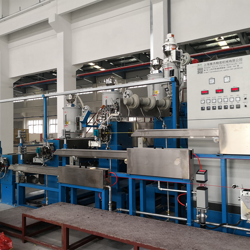
The machine side of that equation matters as much as the steel: stable screw design, a properly sized breaker plate and a head that holds temperature evenly are what let a well-designed die perform. For PE and PVC work, an extruder matched to the die's pressure and output curve removes a whole category of variables from the trial.
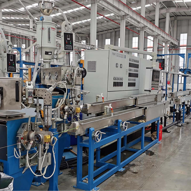
 Full Auto PE/PVC Cable Extruder SystemIntegrated extrusion line for PE and PVC cable insulation, combining automatic pay-off, precision extrusion, cooling, and synchronized haul-off/take-up for stable high-volume production.View Product →
Tolerance Data You Can Actually Quote
Over-specifying tolerance is the most common tooling mistake in the whole design file. The numbers below reflect what a stable profile line holds routinely, not what a laboratory can achieve once.
Hidden Cost Drivers in Tooling Decisions
When a tooling project runs over budget, the die itself is rarely the largest line item. This breakdown reflects the share of tooling-related cost that typically accumulates after the purchase order, and the surprise is that most of it comes from decisions made in the first two weeks of design.
Trial scrap 28%
Die rework 22%
Changeover 19%
Output loss 17%
Late delivery 14%
Trial scrap and die rework together account for roughly half of the overspend, and both trace back to an unbalanced land or an unrealistic tolerance callout. Changeover cost is the quiet one: a die set that needs shims and a full re-heat before every product change quietly consumes production hours for years.
How Tooling Priorities Shift by Application
The same guidelines apply everywhere, but the weighting changes. Cable insulation tooling lives or dies on concentricity, while building profiles live on surface finish and dimensional repeatability across a long run.
- Cable insulation and sheath: 30%
- Building and window profiles: 26%
- Pipe and tube: 18%
- Medical and precision tubing: 14%
- Sheet and film edge trim: 12%
For cable work specifically, the crosshead replaces the profile die as the critical component. Tip and die alignment, melt distribution around the cone and the pressure balance on all sides determine whether the insulation wall stays concentric at 300 m/min. Designers routinely spend more time on the flow channel here than on the land itself.
A Six-Step Tooling Development Sequence
Sequence matters as much as the individual numbers. Each step below closes a variable so that the next trial measures only one thing.
1. Lock the material
Grade, melt index and filler content define shrink, swell and the pressure window. Two suppliers of "the same" compound are not the same.
2. Freeze the cross-section
Walls, radii, hollows and tolerances are signed off before any die drawing exists. Changes after this point cost ten times more.
3. Simulate the flow
A basic flow analysis with the real land geometry exposes unbalanced shear long before steel is ordered.
4. Cut with compensation
Apply shrink and drawdown compensation to the die opening, not to the finished drawing.
5. Trial and gauge
A stable run means 30 minutes without adjustment. Sample from the middle of that window, not the first metre.
6. Freeze the tooling file
Record die drawing, land dimensions, temperatures and screw profile so the next die repeats the result.
Cooling, Sizing and Non-Stop Take-Off
Tooling does not end at the die face. A calibrator that removes heat unevenly will bend a straight profile, and a water bath sized for the wrong line speed will leave the core soft when the part reaches the puller. As a working rule, allow 3–8 m of cooling for typical cable and profile speeds, with vacuum applied in the first 150–250 mm where the melt still has enough strength to be shaped but not enough to sag.
On continuous cable lines the take-off side determines whether the die ever reaches steady state. A properly sized buffer lets the line keep extruding through a reel change, so melt pressure and dimension never see the interruption that would otherwise show up as a thin section 40 metres downstream.
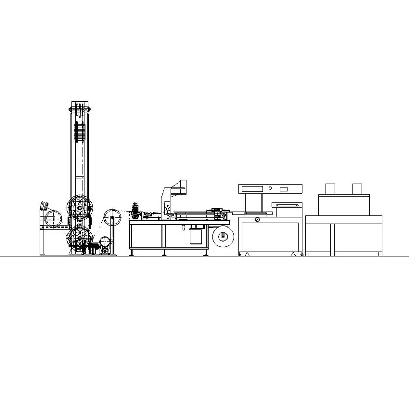 Accumulator Dancer for Continuous Cable LinesVertical or horizontal cable storage unit that buffers payoff and take-up through reel changes, helping maintain line tension and reduce downtime during continuous extrusion.View Product →
The related hardware is worth reviewing alongside the die design: accumulator and dancer systems for continuous extrusion lines hold tension within a few percent while the reel changes, which protects the tolerance band the die was designed to hit. Cooling capacity and screw geometry have to be matched at the same time, since a die that is starved of melt stability will never hold dimension regardless of how well it was cut.
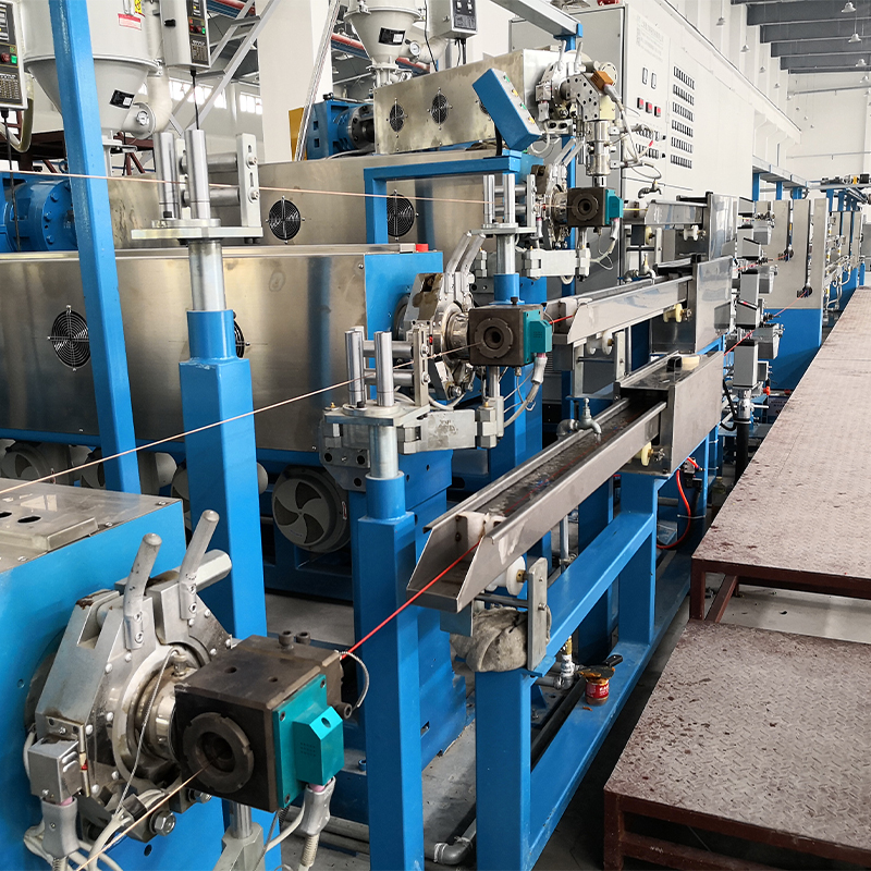 XLPE PE Cable Extruder with Cooling Water TankSingle-screw extrusion and multi-section cooling system for XLPE- and PE-insulated cables, designed for continuous insulation processing with controlled heating and improved cooling consistency.View Product →
Teams comparing machine options will find a useful reference in this high-efficiency PP/PVC/PE extruder guide, which covers the output and pressure relationship that tooling design has to work within.
Maintenance, Changeover and Compliance Practices
A die that performed well at commissioning degrades quietly. Land edges round over, flow-channel polish dulls, and the part drifts half a tolerance band within a year. The practices below keep tooling inside its design envelope.
- Clean with purge compound and brass or copper tools. Abrasive blasting on the land destroys the edge radius that controls surface finish.
- Measure land wear every 500 running hours. More than 0.02 mm of wear is enough to shift a cross-section dimension.
- Store die and tip as a matched, tagged set. Mixing components between sets reintroduces concentricity error on cable work.
- Record melt temperature and pressure at each start-up. A rising head pressure trend signals partial blockage long before scrap appears.
- Keep material certificates and process records with the tooling file — insulation wall thickness on cable products is a compliance item, not just a quality preference.
- Re-check guarding and heat-zone interlocks whenever a die set is changed, since head hardware is removed and refitted frequently.
Good extrusion tooling design is mostly restraint. Uniform walls, balanced lands, honest tolerances and a documented trial will outperform any amount of on-machine tuning, and they make the next die cheaper to build because the file already contains the answers. Start with the cross-section, not the die drawing, and the rest of the project tends to follow.