LANGUAGE
 中文简体
 русский
 Français
 Español
 Português
 عربى

Content
- 1 The plastic extrusion process, step by step
- 2 Screw zones: what each one has to get right
- 3 Material comparison: what changes between PVC, PE and XLPE
- 4 Hidden metrics: where wall variation actually comes from
- 5 Where extruded output goes
- 6 Specifying a line: the sequence that avoids rework
- 7 Maintenance and compliance routines that protect the process
A 90 mm single-screw extruder running plasticized PVC over a 2.5 mm² conductor will hold jacket wall thickness inside ±4% for hours — until the screen pack loads, melt pressure climbs 6 MPa and output sags, even though nobody has touched a setpoint. Most faults blamed on the die are really heat, pressure and drag-flow faults that only surface at the die.
The short answer
Three variables decide whether a plastic extrusion process stays in control: melt homogeneity leaving the metering zone, die pressure stability, and the cooling rate in the first 300 mm after the die. Screw geometry sets the first, screen pack and die design set the second, water temperature and line speed set the third. Take-up, winding and packaging can only preserve or destroy what those three produce.
Everything downstream is arithmetic. A 3% swing in output becomes a 3% swing in wall thickness unless line speed compensates, and most haul-off controllers react 4–8 seconds late — long enough for 20 m of off-spec product on a 30 m/min line.
The plastic extrusion process, step by step
Extrusion is a drag-flow process. The screw does not so much push plastic forward as drag it around the barrel and let the axial pressure gradient move it toward the die. That single distinction explains most shop-floor surprises.
- Feeding and dosing. Resin arrives as pellets or granules and passes a gravimetric or volumetric doser. A gravimetric unit holds ±0.5%; a volumetric one drifts with bulk density, which shows up as a slow wall-thickness trend nobody can trace.
- Conveying in the feed zone. Flights are deep here so the channel moves solids, not melt. A grooved feed throat raises friction against the barrel and stabilises output on HDPE grades where smooth-bore machines surge.
- Melting in the compression zone. Barrel heaters start the phase change and shear finishes it. A compression ratio of 2.5:1 to 3.5:1 squeezes the solid bed; unmelted pellets that survive this zone reappear downstream as surface roughness and electrical weak points.
- Metering and pumping. The shallow metering channel builds the pressure that forces melt through the screen pack and die. This is where output stability is decided, and where flight wear quietly costs 3–5% throughput before anyone notices.
- Forming at the die. A crosshead or tube die gives the melt its final section. For cable coating, draw ratio balance near 1.0 keeps insulation concentric; push above 1.2 and you start chasing eccentricity with die rework.
- Cooling, sizing and take-up. Water temperature, bath length and capstan speed lock in the final dimensions. Cool too fast and thick sections trap voids; cool too slowly and the bath becomes the line bottleneck.
Screw zones: what each one has to get right
A general-purpose screw runs 24:1 to 30:1 L/D, with barrier or mixing sections added when output climbs or colour changes get frequent. The three functional zones carry different risks.
Feed zone
Deep channel — roughly 10–13% of screw diameter on a 90 mm machine. Governs bite and throughput; too shallow and the screw starves, too deep and the solid bed collapses.
Compression zone
Typically 25–40% of the screw length. Compression ratio and flight pitch determine melt quality; a badly matched section leaves gels that only show up after a 24-hour insulation resistance test.
Metering zone
Shallow channel pumping against 10–35 MPa die pressure. Measure flight outside diameter every 2,000 hours; 0.3 mm of wear is enough to shift the operating curve.
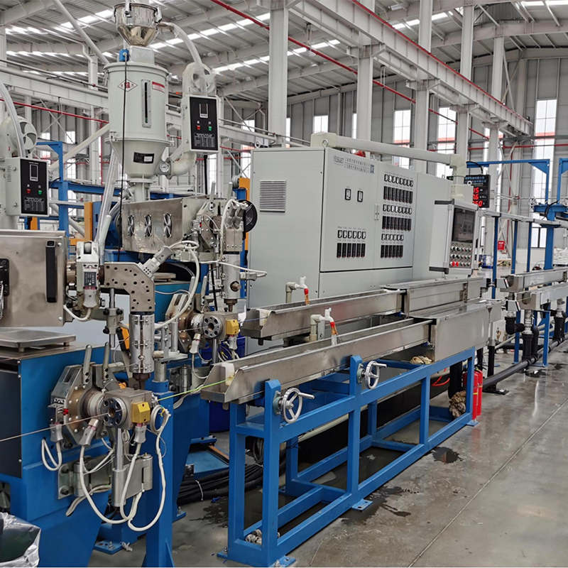
Barrel profiles matter as much as the screw itself. A high-efficiency PP/PVC/PE cable extruder normally pairs a barrier screw with four or five separately controlled heating zones so the compression section can be trimmed without disturbing the metering temperature — a comparison of configurations is covered in this extruder selection guide.
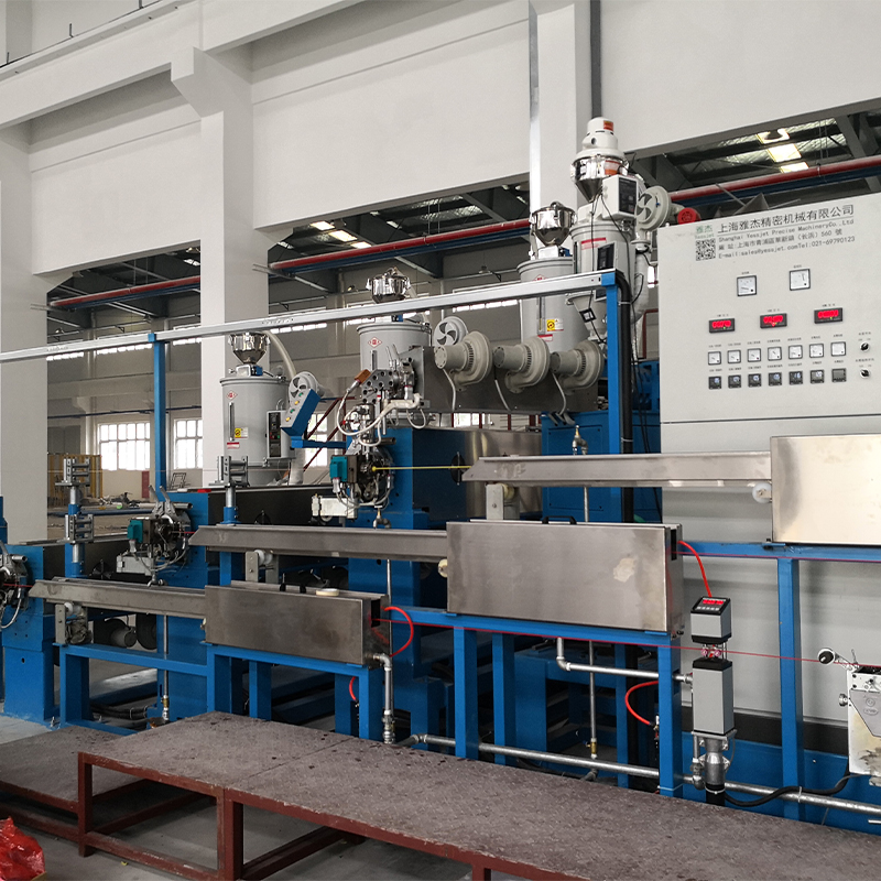 High-Efficiency PP/PVC/PE Cable Extrusion MachineReview it when comparing barrel heating configurations for PP/PVC/PE cable lines; it offers stable multi-material extrusion and 240 kg/h output.View Product →
Material comparison: what changes between PVC, PE and XLPE
The machine stays the same; the window does not. These are working ranges for cable and profile extrusion — the narrow bands are where scrap rates double.
Material
Melt at die
Cooling
Wall tolerance
Watch out for
Plasticized PVC
165–185 °C
Water 20–35 °C
±5%
Plate-out on flights, HCl corrosion
HDPE
190–215 °C
Graded 25–45 °C
±4%
Die swell, sharkskin at high shear
XLPE
200–235 °C
CV tube or pressurised water
±5%
Scorch, moisture in compound
PP
200–230 °C
Water 20–30 °C
±5%
Post-extrusion shrinkage
PA12
230–260 °C
Hot water or air
±6%
Pre-dry below 0.05% moisture
Crosslinked PE adds a second process after the die: the melt enters a heated tube where peroxide decomposes and the polymer network forms before cooling. An XLPE/PE cable extruder with an integrated water tank and controlled cooling gradient keeps the crosslinking front stable; a 5 °C drift in tube temperature is enough to move the scorch boundary by metres.
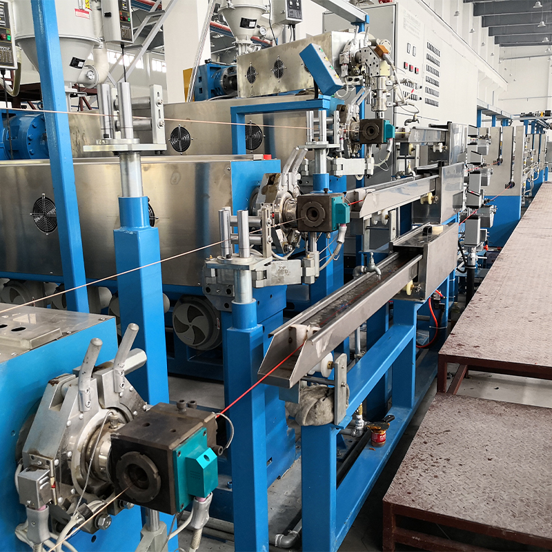 XLPE/PE Cable Extruder with Cooling Water TankIntegrated multi-section water cooling supports stable XLPE/PE insulation extrusion, helping address uneven thickness and slow cooling on power, communication, and automotive cable lines.View Product →
Hidden metrics: where wall variation actually comes from
Sorting three months of scrap data across typical extrusion lines puts the blame in a predictable order. Tooling is rarely first.
Feed & screw
34%
34%
Melt temp
26%
26%
Die wear
18%
18%
Capstan
14%
14%
Resin lot
8%
8%
Two of the top three causes sit upstream of the die and neither appears on a standard dashboard. Melt pressure trending upward at constant screw speed means the screen pack is loading; melt pressure trending downward means the feed throat is starving or the flights are worn. Both are visible weeks before a customer complaint.
Where extruded output goes
Line architecture follows the end market. Cable work needs crossheads, accumulators and long cooling; profile work needs vacuum calibration and precise haul-off.
- Cable insulation and jacketing — 34%. Crosshead dies, conductor preheat, tight concentricity.
- Pipe and tubing — 22%. Vacuum sizing tanks and long cooling troughs.
- Film and sheet — 20%. Flat dies, chill rolls, thickness gauging.
- Profiles and trim — 16%. Calibration, haul-off tension, cut-length accuracy.
- Filament and coating — 8%. Fine filtration and diameter control.
Specifying a line: the sequence that avoids rework
1. Fix output and product range first. Tonnes per hour and conductor or profile cross-section decide screw diameter. Buying a 120 mm machine for a 60 mm job costs 30% more in specific energy on every kilogram.
2. Match screw and barrel to the material. Barrier screws for PE and XLPE, gentler profiles for rigid PVC. Confirm the heating zone count and whether the compression section can be trimmed independently.
3. Size the die and crosshead for draw ratio balance. Ask for a DRB calculation across the whole product range, not a single point. Most eccentricity complaints trace back to a die sized for one wall thickness.
4. Set cooling length from line speed, not floor space. A rough rule is 0.8–1.2 m of trough per m/min for thin wall PVC. Undersized cooling forces you to slow the line and give away capacity.
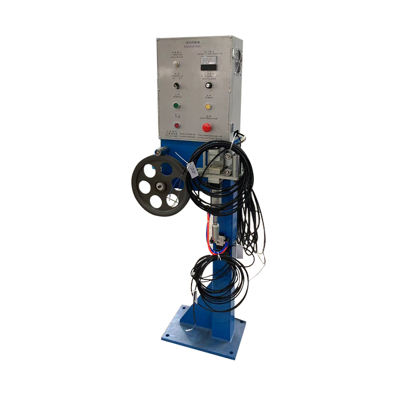
5. Plan for continuous operation. A reel change on a 30 m/min line needs 90 m of buffer; accumulator and tension dancer systems hold that without dropping extruder speed, which is why they are usually specified together with the complete wire and cable extrusion line rather than added later.
6. Close the loop at the end of the line. Coiling, wrapping and palletising determine headcount per shift far more than extruder throughput does once a line is running steadily.
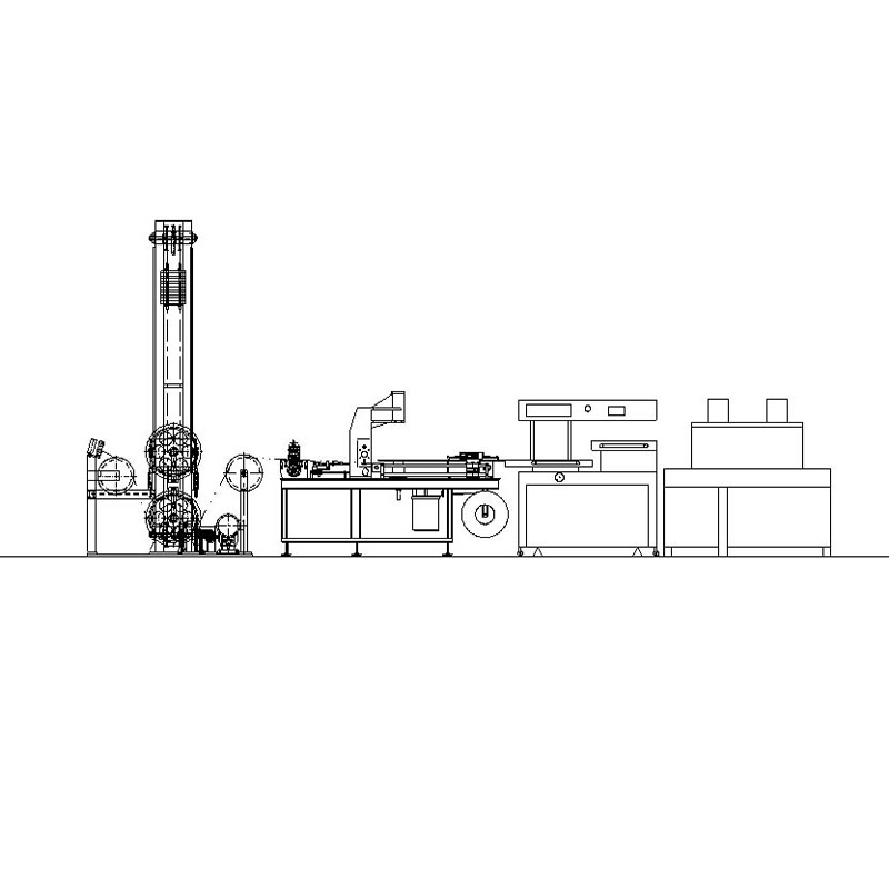 Accumulator Dancer Cable Storage RackVertical or horizontal storage for extrusion, CV, and rewind lines, it controls payoff or take-up during reel changes and helps reduce changeover downtime.View Product →
Maintenance and compliance routines that protect the process
Extrusion rewards boring discipline. These checks are short, and skipping them is what turns a stable line into a variable one.
- Every shift: log melt pressure and screw speed together; a pressure rise above 5–8 MPa across a clean screen pack signals contamination or a failing heater band.
- Monthly: verify thermocouple accuracy against a calibrated probe, check barrel heater continuity, and inspect water bath pH and scale — hard water films cut heat transfer and drift dimensions.
- Every 2,000 hours: measure screw flight clearance and barrel bore wear, replace worn screens, and re-torque die bolts after thermal cycling.
- Annually: audit guarding, emergency stops and interlocked doors against the applicable machinery directive, and keep calibration and material traceability records for cable orders that require them.
- Per material change: purge with a compatible purging compound rather than raising temperature, which degrades PVC and leaves carbon deposits that shed into the next run.
A plastic extrusion process is only as repeatable as the records kept around it. When the same setpoints, the same water conditions and the same screw clearance produce the same wall thickness three months apart, the line is genuinely under control — and every downstream automation decision becomes a capacity question rather than a quality one.