LANGUAGE
 中文简体
中文简体 русский
 Français
 Español
 Português
 عربى
عربى
Content
- 1 What the Heating-Rate Check Really Compares
- 2 Hidden Indicators: Which Fault Dominates in Real Service Records
- 3 Sensor and Heater Combinations: Measured Trade-offs
- 4 Where Slope Faults Cluster Across Cable Products
- 5 A Five-Step Repair Sequence and What Each Step Costs
- 6 Maintenance Intervals and Records That Survive an Audit
At 06:40 the line stopped. A 90 mm PVC extruder that had been running 2.5 sq mm building wire at 780 m/min for eleven hours tripped on a heating-rate fault: zone 3 held 163 °C against a 175 °C setpoint, and every restart ended in the same shutdown four minutes later. The crew replaced the heater band first. Nothing changed. The real fault was a twelve-year-old thermocouple with a loose crimp, reading 11 °C low.
The short version: "heater extruder not heating at expected rate" is a slope test, not a temperature alarm. The controller compares how fast a zone warms against how fast it should warm, and trips when the measured slope falls short of the configured floor. On cable extrusion lines the majority of these events trace back to measurement or power-switching faults rather than a dead element, so proving the sensor before touching the heater saves the most time.
That distinction carries a price tag. A wrong heater diagnosis costs one band, one hour and a scrapped reel. A missed wiring fault costs a repeat outage, because a loose thermocouple drifts again the moment the barrel reaches operating temperature and the conductors expand.
What the Heating-Rate Check Really Compares
The check is a self-test inside the temperature loop. The controller samples zone temperature every half second to one second, keeps a short rolling buffer, and computes the slope in degrees per second. During warm-up it expects a minimum slope; if the measured slope stays below that floor for the entire window, it cuts heater power and reports the fault. Two settings decide sensitivity: the window length, commonly 10 to 20 seconds, and the minimum acceptable gain. Widen the window too far and a genuine element failure hides inside it; narrow it too far and normal overshoot trips the alarm.
Because the test watches only the slope, three very different faults produce exactly the same message on the HMI.
Heat input lost
An open heating element, a blown semiconductor fuse, a solid-state relay that no longer conducts, pitted contactor tips, a tripped thermal cut-out, or a zone that was undersized for the throughput from the day it was installed.
Heat leaving too fast
A cooling fan still running during warm-up, a jacket water leak, an open die head, a large cold thermal mass, or a plant door propped open in winter. The heater is fine; the load is not.
The measurement is wrong
Thermocouple drift, reversed polarity, the wrong sensor type selected in the parameters, a loose crimp, a damaged compensating cable, or a shield grounded at both ends. The barrel is hot; the signal is not.
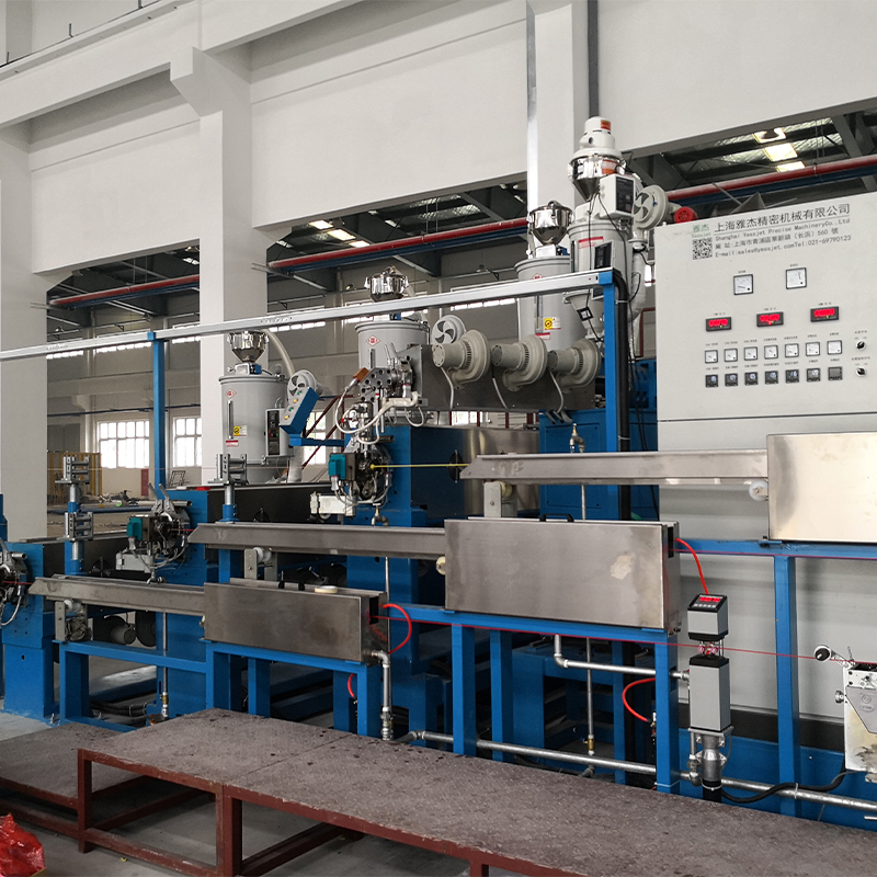
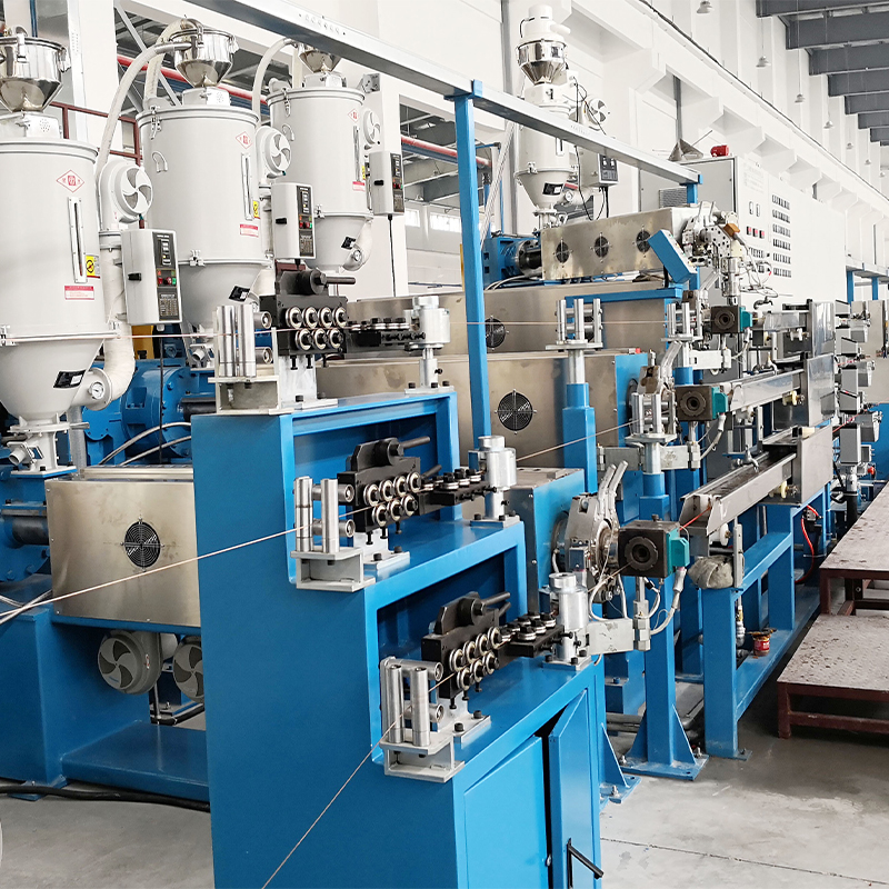
A five-zone barrel makes isolation straightforward. On machines such as the full-auto PE/PVC high-performance cable extruder, every zone carries its own thermocouple and its own slope window, so one loose terminal shows up as a single misbehaving zone while its neighbours hold steady.
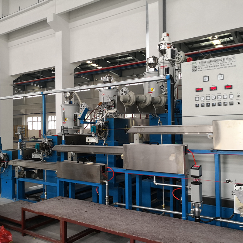 Full Auto PE PVC High-Performance Cable ExtruderIntegrated PE/PVC extrusion system with PLC control and multi-zone temperature monitoring for stable, high-precision cable insulation production.View Product →
Hidden Indicators: Which Fault Dominates in Real Service Records
Across several hundred logged events on PVC, PE and XLPE lines, the split is lopsided. The chart below is drawn from maintenance tickets where the root cause was confirmed by measurement rather than guessed.
38% Sensor
22% Relay
18% Element
12% Settings
10% Cooling
The measurement bucket dominates because thermocouples fail slowly. A type K junction oxidises and the error creeps up by two or three degrees a year, invisible on a stable line but fatal once a slope window is tightened or a new material runs hotter.
The second bucket is power switching. Solid-state relays usually fail partially: the device still conducts, but with higher on-resistance, so the zone heats at roughly 60 percent of its normal slope. It passes the check at 120 °C and fails at 170 °C, which is why the alarm often appears only on the last zone or during a cold morning start.
Sensor and Heater Combinations: Measured Trade-offs
Selection usually comes down to response time against stability. A slow sensor inside a short slope window raises the same fault even when the heater is perfectly healthy.
Note: these are representative values measured from a cold start on a 90 mm barrel; real tolerances shift with barrel mass, ambient temperature and sensor insertion depth.
On high-output lines the decision is usually driven by throughput rather than by the alarm. Heater band and element selection for those machines is covered in more detail in this guide to high-efficiency PP/PVC/PE cable extruders.
Where Slope Faults Cluster Across Cable Products
The product mix on the plant floor changes which fault appears first. Thin insulation on data cable reacts to a two-degree error, while a thick XLPE wall absorbs far more before the defect shows.
- PVC building wire: 34 percent
- XLPE power cable: 26 percent
- LAN and data cable: 18 percent
- Automotive and electronic wire: 14 percent
- Other and specialty compounds: 8 percent
The first two slices behave differently. PVC building wire runs at lower melt temperatures, where type J sensors dominate and moisture in the terminal head is the usual culprit. XLPE power cable runs hotter and is quenched immediately after the die, so a heat-rate fault there also disturbs the cooling profile that sets insulation crystallinity.
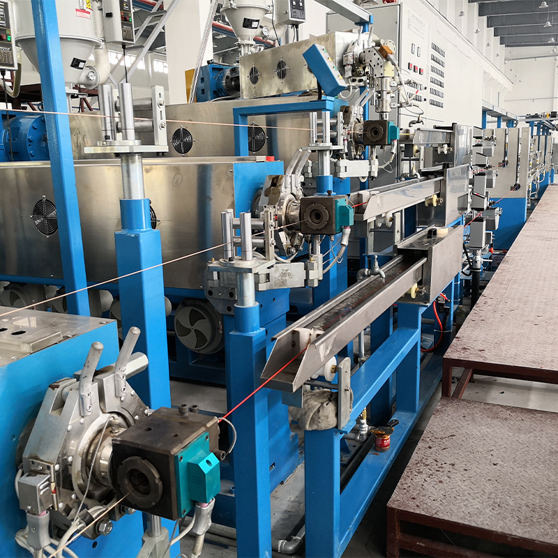 XLPE PE Cable Extruder with Cooling Water TankIntegrates single-screw extrusion, temperature-controlled heating, and multi-section water tank for continuous XLPE/PE cable insulation with stable cooling and thickness control.View Product →
A Five-Step Repair Sequence and What Each Step Costs
Work in this order and most faults are found in under forty minutes, without opening a single heater band.
- Prove the reading. Clamp a calibrated meter at the terminal head and compare it with the HMI. A disagreement of ten degrees or more points to the sensor or its wiring, not the element.
- Check the power path. Measure current on each leg during warm-up. A healthy zone draws a stable current; a failing relay shows a current that sags as the zone heats.
- Check the heat loss. Fan running during warm-up, die head open, water leaking into the jacket, barrel cold, door open.
- Check the parameters. Sensor type, slope window, minimum gain and PID limits. A controller swapped in from another machine often carries a different sensor type in its configuration.
- Re-tune downstream. After a sensor change the melt temperature shifts slightly, so verify tension and diameter before releasing the reel.
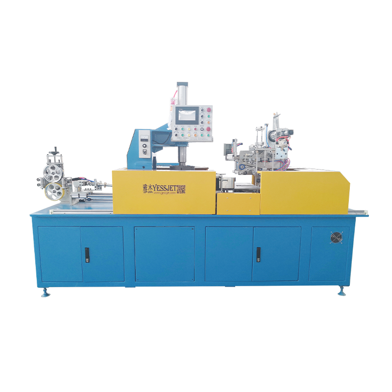
That last step is the one most crews skip. Once heat input is stable, melt viscosity settles and the downstream pull has to stay constant through every speed change, which is exactly what a dedicated tension control system is built to hold.
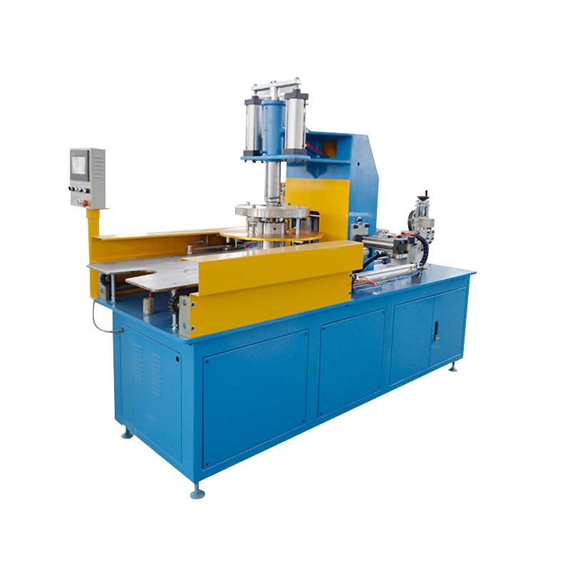
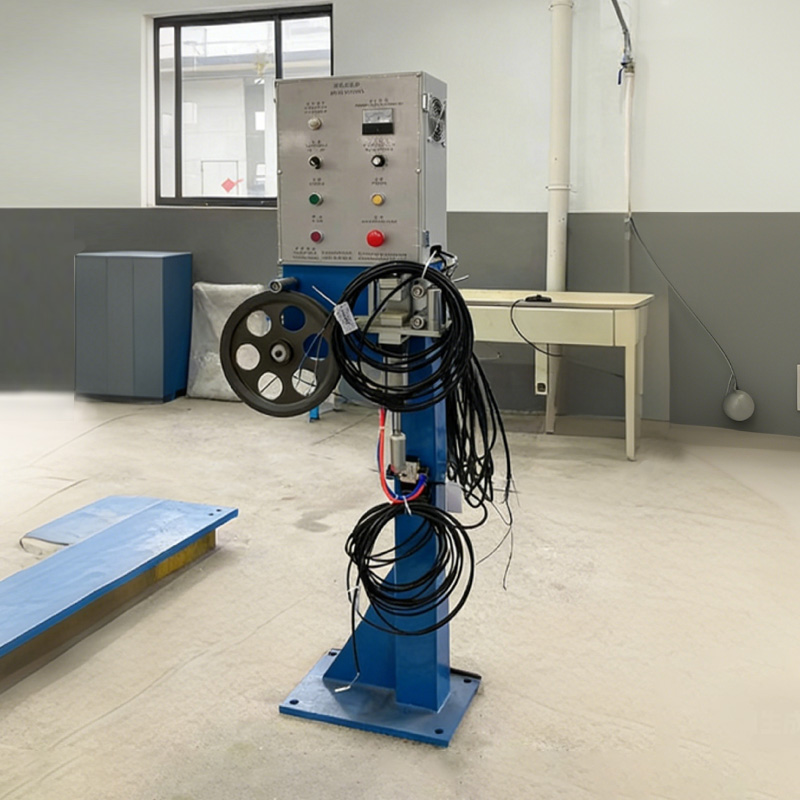 Wire Cable Tension Control System for Stable WindingReal-time tension regulation accessory for cable winding, helping prevent stretching or loose reels and maintain consistent downstream pull during speed changes.View Product →
Reactive repair
One unplanned hour on a 90 mm line plus one scrapped reel, repeated every four to six weeks while the drifting sensor stays in service. The cost is hidden in the restart scrap, not in the spare part.
Planned programme
Annual calibration, a monthly infrared scan, and spare thermocouples and bands on the shelf. Faults are found at scheduled stops, when a two-hour repair window costs nothing.
Maintenance Intervals and Records That Survive an Audit
A slope fault is a symptom that rewards routine attention. These intervals cover the majority of failures logged on cable extrusion equipment.
- Monthly: infrared scan of terminal blocks and relay connections on loaded zones, looking for a rise above the surrounding baseline.
- Quarterly: torque check on heater band terminals to the manufacturer figure, because thermal cycling loosens them steadily.
- Annually: three-point calibration of every zone thermocouple and replacement of anything drifting beyond three degrees.
- Annually: trip test of the thermal cut-out and verification that over-temperature protection works independently of the control loop.
- Continuously: log zone current signatures so a drift trend is visible weeks before it becomes a shutdown.
The compliance side matters more than most operators expect. Machines shipped into Europe or North America must demonstrate that the safety limiter is independent of the control thermocouple, and that test records can be produced on request. Calibration sheets, element replacement dates and cut-out test logs are the evidence, and they are cheap to keep if the habit starts when the machine is installed.
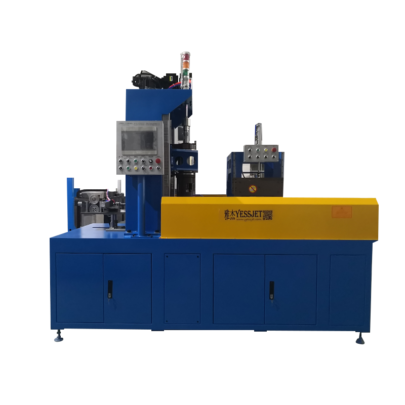
If the line genuinely cannot stop for a sensor swap, a storage accumulator buys the few minutes required to open a terminal head while the extruder keeps turning: accumulator and dancer systems for continuous extrusion lines hold enough material to bridge a short interruption without a cold restart.
Treat "heater extruder not heating at expected rate" as a measurement question first, a power question second, and a heater question last. That order matches where the faults actually live, and it turns a four-hour line stoppage into a forty-minute check.