LANGUAGE
 中文简体
中文简体 русский
 Français
 Español
 Português
 عربى
عربى
Content
- 1 What the Compression Ratio Actually Measures
- 2 Matching the Ratio to the Compound You Run
- 3 Comparing Typical Cable Extrusion Screw Setups
- 4 What the Nameplate Number Does Not Show
- 5 Where Compression Ratio Carries the Most Weight
- 6 Selection Workflow: From Compound Data to Screw Order
- 7 Wear, Maintenance and Compliance Notes
A cable plant replacing the screw on a rigid PVC insulation line once ordered a 4.0 compression ratio, on the reasonable-sounding logic that more compression means better melting. Within three shifts the extruder was surging, melt temperature had climbed by roughly 18 °C, and scorched specks were reaching the die. Nothing was broken. The screw was compressing a compound that had already reached melt density back in the feed zone, and the extra work came out as heat.
Short answer: compression ratio (CR) is the volume of the first feed flight divided by the volume of the last metering flight, which on a constant-pitch screw is nearly the same as feed channel depth divided by metering channel depth. General-purpose screws run between 2.0 and 4.0. Rigid PVC normally sits at 2.0-2.5, plasticized PVC and HDPE at 2.5-3.5, PP at 3.0-3.5, and heavily filled halogen-free compounds are usually better served by a mixing section than by a higher number.
The sections below show how that number is built, what it quietly controls on a cable line, and how to specify it without ordering a second screw.
What the Compression Ratio Actually Measures
A full-flight screw works in three zones. The feed zone keeps a deep, constant channel so loose pellets can drop in and be conveyed forward. The compression, or transition, zone tapers that channel and squeezes the solid bed as it melts. The metering zone returns to a shallow, constant depth so the melt reaches the die at a stable pressure and a predictable rate.
Compression ratio compares the first and last of those volumes. Because pitch and flight width stay constant on a standard full-flight screw, the volume ratio collapses into a depth ratio: CR = H1 / H2, where H1 is the feed channel depth and H2 the metering channel depth.
The physical job behind the number is density. Cable compound pellets have a bulk density of roughly 0.5 to 0.7 g/cm3, while the same polymer as a melt sits near 0.9 to 1.3 g/cm3. The material itself therefore needs only about a 1.6 to 2.2 volume reduction to become a void-free melt. Compression above that figure compensates for leakage flow over the flight lands, for the pressure the die requires, and for batch-to-batch variation in how the feed behaves.
Where a nameplate number can mislead
A depth ratio is only valid for constant pitch and constant flight width. Once pitch changes, or a barrier flight or Maddock-style mixer is added, the real ratio has to come from actual channel volumes. On variable-pitch screws, a quick depth ratio can overstate the effective CR by 10 to 15 percent, which is enough to push a PVC screw out of its safe window. Cable extruders are therefore specified per compound rather than per barrel size, and the screw drawing should state which calculation method was used.
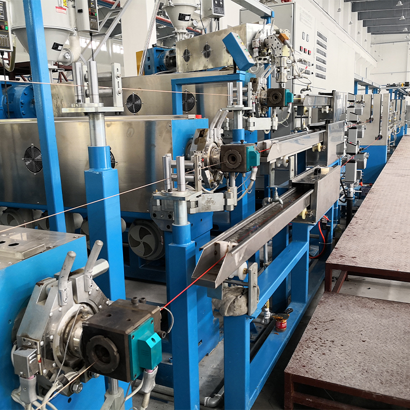
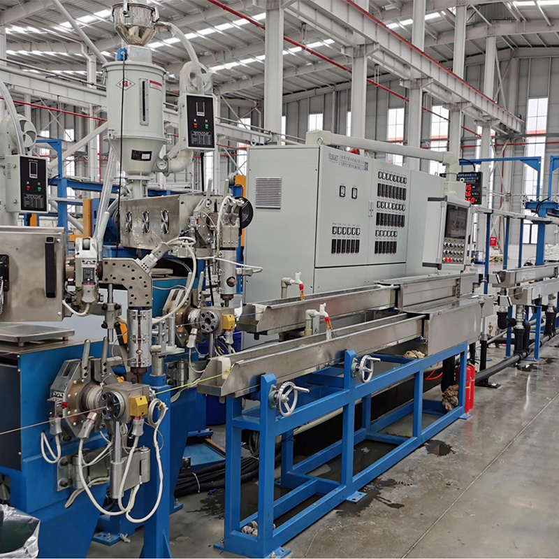
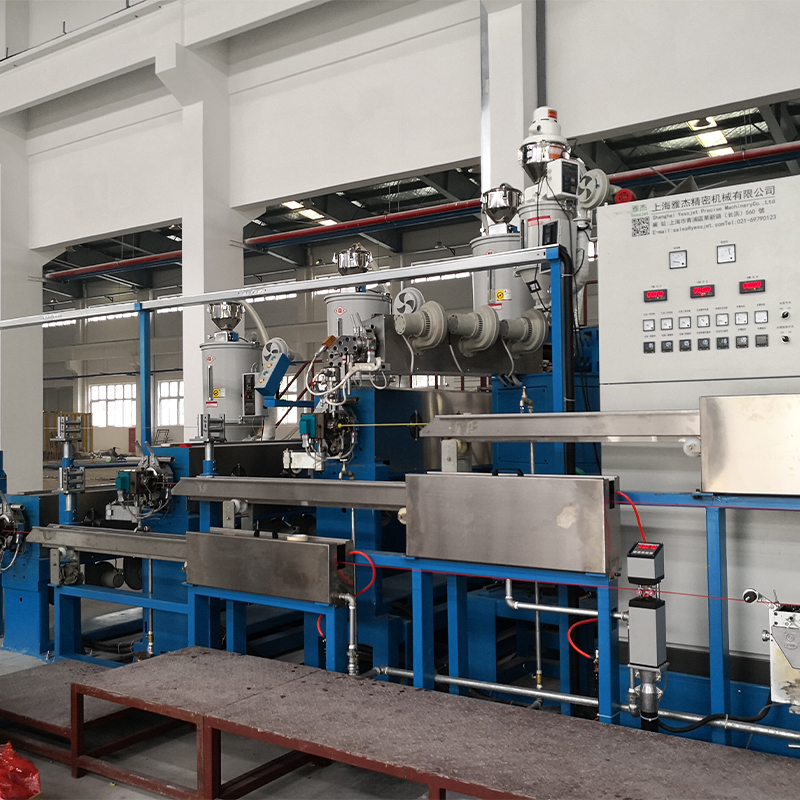 High-Efficiency PP PVC PE Cable ExtruderAs a multifunctional core device for cable production, the High-Eff PP PVC PE Cable Extruder is engineered for energy-saving, high-yield extrusion of insulation layers...View Product →
Matching the Ratio to the Compound You Run
Cable compounds are not interchangeable, and compression ratio is where that difference becomes mechanical. Three variables drive the choice: how far bulk density falls as the material melts, how much shear heat the polymer tolerates, and how abrasive the formulation is.
Rigid and plasticized PVC
Unplasticized PVC is the most shear-sensitive material on a cable line and normally runs at 2.0-2.5 with a long, gentle transition. A higher ratio creates local hot spots that release hydrogen chloride and leave burn marks inside a thin insulation wall. Flexible PVC tolerates 2.5-3.0, although plasticizer volatiles make the feed zone worth watching.
PE, HDPE and PP
Polyolefins have higher melt viscosity and cleaner melting behaviour, so they accept 2.8-3.5 without complaint. HDPE sheathing screws often pair that ratio with a deep feed section and a 25:1 to 30:1 L/D so the line can run hard while the melt stays homogeneous.
XLPE and crosslinkable compounds
Peroxide-cured XLPE is a special case. The crosslinking agent is sensitive to residence time and temperature, so the screw must build pressure without dumping shear heat into the melt. A ratio near 2.3-3.0, a smooth transition and tight temperature control matter more than raw output. Compounds already close to the pre-cure threshold show gels and lumps rather than a clean melt.
Filled, flame-retardant and halogen-free compounds
High filler loading raises bulk density, reduces the volume change the screw has to create, and wears flights at the same time. A 2.5-3.5 ratio combined with a barrier or dispersive mixing section beats simply pushing the number higher.
Screw-and-barrel pairing across these families follows a fairly predictable pattern; this guide to high-efficiency PP, PVC and PE extrusion covers the combinations in more detail.
Comparing Typical Cable Extrusion Screw Setups
The comparison below summarises the windows cable extruder builders work with most often. Treat the figures as starting points for a quotation rather than universal constants, because compound suppliers revise formulations and bulk density moves with them.
Typical compression ratio windows for common cable compounds; confirm the final geometry against the current compound data sheet before ordering.
What the Nameplate Number Does Not Show
Two screws with the same stated ratio can behave nothing alike, because the line responds to energy and pressure rather than to geometry alone. When CR is too low, the solid bed reaches the metering zone only partly melted and output swings as unmelted fragments pass the die. When it is too high, the same instability returns from the opposite direction as melt temperature and torque climb.
Insulation wall thickness is the fastest indicator of both problems. The chart below reflects a 65 mm PE sheathing screw run across a range of compression ratios; the values show the shape of the effect rather than a specification for any particular line.
4.2%
CR 2.0
2.6%
CR 2.5
1.2%
CR 3.0
2.1%
CR 3.5
4.8%
CR 4.0
Three metrics sit behind that curve. Melt pressure stability comes first: a fluctuation of more than about one percent at the die shows up as wall thickness scatter. Specific energy comes second: compression that is doing useful melting work keeps kilowatt-hours per kilogram flat, while compression that only generates shear drives the figure up. Screw wear is third, because a worn metering flight quietly raises the effective ratio over a year of production.
Where Compression Ratio Carries the Most Weight
Every extrusion screw has a compression ratio, but the number dominates specification decisions in some cable segments far more than in others.
- 36% PVC insulation and sheathing
- 24% PE and halogen-free sheathing
- 22% XLPE power cable insulation
- 18% LAN and data cable
The pattern follows compound sensitivity rather than cable volume. PVC takes the largest share because its processing window is narrow and a wrong ratio appears immediately as discolouration or surface defects. PE and halogen-free sheathing follows, driven by abrasion and dispersion rather than heat sensitivity. XLPE power cable screws are specified conservatively because the crosslinking chemistry sets the ceiling. LAN and data cable, with thin walls and tight capacitance targets, depends on pressure stability above everything else.
For XLPE and PE sheathing work, a screw specified together with its cooling arrangement is usually the safer starting point.
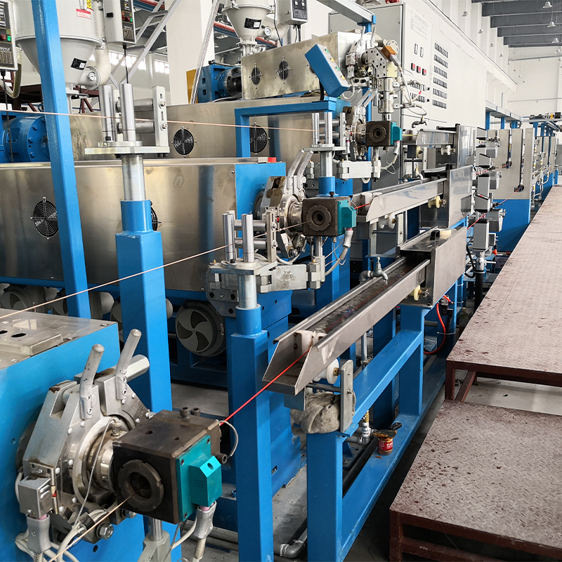 XLPE PE Cable Extruder with Cooling Water TankThis XLPE PE Cable Extruder w/Water Tank is engineered for extrusion and cooling of XLPE and PE insulated cables, integrating a high-precision single-screw extruder, t...View Product →
Selection Workflow: From Compound Data to Screw Order
Six steps turn compound data into a usable screw specification.
- Ask the compound supplier for bulk density, melt density, melt flow rate and the recommended processing range. The bulk-to-melt density ratio sets the floor for a sensible compression ratio.
- Define the product before the machine: insulation or sheath, wall thickness, tolerance band, conductor size and the line speed you intend to run.
- Fix L/D and output first. Compression ratio follows from the feed and metering channel depths, so deciding it in isolation forces a compromise elsewhere.
- Check transition length and shear rate, not only the ratio. A 2.8 ratio spread over a long transition behaves very differently from the same ratio concentrated in three flights.
- Decide whether the compound needs a barrier flight, a Maddock section or a pin mixer; filled and heavily coloured compounds often gain more from dispersion than from compression.
- Confirm pitch, flight width, case depth, wear allowance and the calculation method on the drawing, and get the effective compression ratio in writing.
Once the screw geometry is fixed, the rest of the line has to match it. Cooling length, take-up tension, accumulator capacity and coiling speed all follow from a stable melt output.
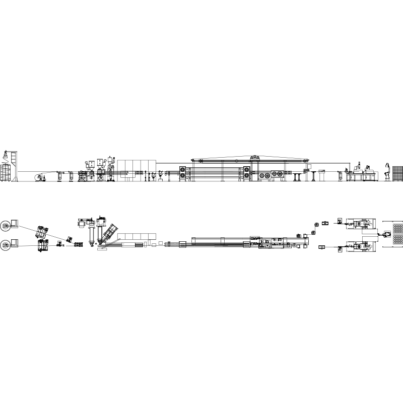 Wire And Cable Extrusion LineFeatures 1. Barrel and Screw import from Taiwan with high extrude capacity. 2. Different type of plastic material could choose their own barrel and screw.EX: PVC, PE, ...View Product →
Wear, Maintenance and Compliance Notes
A screw is a wear part, and its compression ratio drifts. Nitrided flights lose case depth against filled compounds, and once the metering channel becomes a few tenths of a millimetre deeper, the effective ratio falls and the melting behaviour changes with it. Lines that were stable at commissioning begin to show wall thickness scatter, and the cause is often the screw rather than the compound.
- Measure flight outer diameter and channel depth at every annual shutdown and compare the readings with the original drawing.
- Track specific energy per kilogram; a slow upward trend is one of the earliest signs of wear and of a shifting compression ratio.
- Keep the screw drawing, material grade and heat treatment records together so a replacement can be quoted without re-engineering.
- Re-check the barrel heating profile and any screw cooling whenever the compound changes; both can offset modest geometry limits without a new screw.
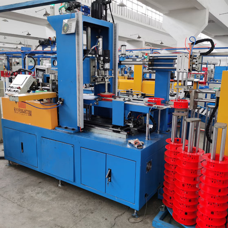
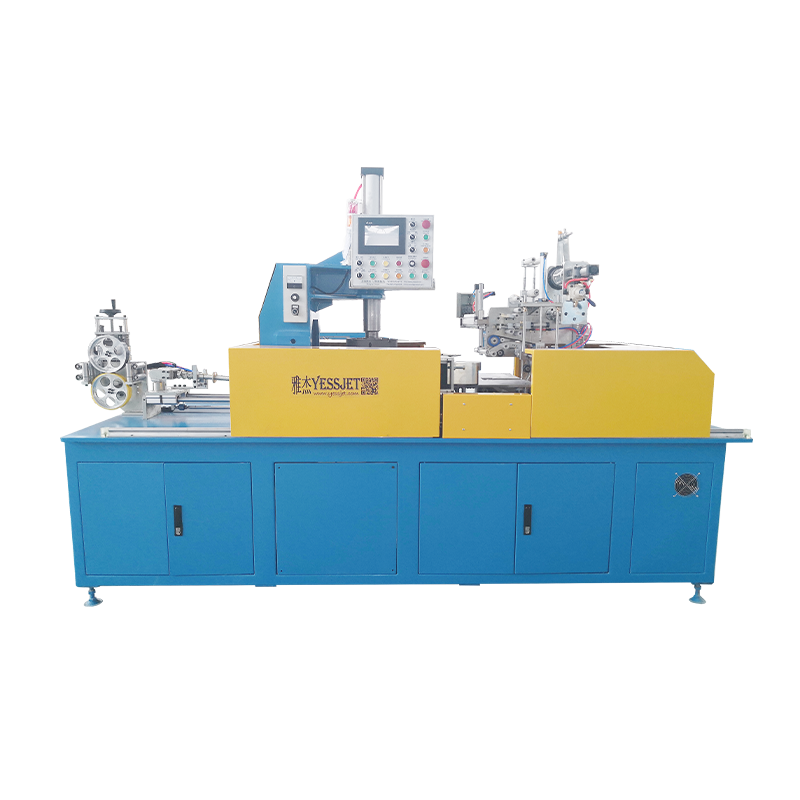
Uptime also depends on buffering screw output downstream. Accumulator and dancer systems for continuous extrusion lines hold material through reel changes so the extruder never has to stop, which keeps melt history consistent from the first metre to the last.
Compression ratio is one number that decides where a screw does its melting work. Match it to the density change and shear tolerance of the compound, keep the transition long enough to melt without scorching, and verify real channel volumes instead of trusting a depth ratio taken from a drawing. On a cable line, that is usually the difference between a stable insulation wall and a week of scrap.