LANGUAGE
 中文简体
 русский
 Français
 Español
 Português
 عربى

Content
- 1 The Working LLDPE Temperature Range, Zone by Zone
- 2 Why a 120–130 °C Melting Point Still Needs a 200 °C Die
- 3 How LLDPE Compares With LDPE, HDPE and XLPE
- 4 Where Temperature Problems Actually Show Up
- 5 Why the Resin Grade Matters as Much as the Temperature
- 6 Start-Up and Shutdown Sequence That Protects the Window
- 7 Hardware That Holds the Window Steady
- 8 Maintenance, Records and Compliance
Two hours into a night shift, a 90 mm extruder running a 1 kV LLDPE-insulated cable started producing a matte, slightly wavy surface. Screw speed was steady, the diameter scanner was correcting every few seconds, and head pressure had climbed 18 bar above the morning's baseline. The barrel set points had simply been copied from an LDPE job: 165/175/185/190 °C with a 195 °C die.
The compound was not the problem. The temperature window was. LLDPE runs hotter and flatter than LDPE, and it punishes mistakes in both directions: too cold leaves unmelted gels and pressure surges, too hot brings die drool, oxidation and a measurably weaker insulation wall.
The short answer
LLDPE melts between 120 and 130 °C, but it is processed at a melt temperature of 180 to 230 °C. The die usually sits 10–20 °C above the metering zone. For cable insulation, hold the measured melt at 205–215 °C and never let it dwell above 240 °C.
The Working LLDPE Temperature Range, Zone by Zone
The 120–130 °C figure is an equilibrium melting point measured by DSC. It tells you where the crystals disappear, not where the polymer flows well enough to coat a conductor at 200 m/min. Between melting and good flow there is a 60–90 °C gap, and the profile below is what actually closes it.
Two corrections matter more than the absolute numbers. First, heater band readings sit 10–25 °C below real melt temperature because of shear heating in the screw, so a barrel showing 195 °C may be delivering a 215 °C melt. Second, LLDPE is shear-thinning: raising melt temperature lowers viscosity and pressure, but it also lowers melt strength, which shows up later as sag on the cone and ovality in the finished coil.
Why a 120–130 °C Melting Point Still Needs a 200 °C Die
Four mechanisms explain the gap between the datasheet number and the set points on the panel.
A narrow melting window
LLDPE's short-chain branching distribution makes most crystals melt within roughly 10 °C. There is no long softening phase as with LDPE, so the solid-to-flow transition is abrupt and the early zones must already carry heat.
Viscosity, not just phase
A fully melted but cold melt is still too viscous to spread evenly around a 2.5 mm insulation wall. Die temperatures of 200–225 °C bring viscosity down to where the polymer relaxes before it leaves the land length.
Shear heat is part of the budget
Roughly a third to a half of the energy that melts a PE screw's charge comes from mechanical work, not heater bands. That is why a worn screw suddenly needs 15 °C more on the panel to reach the same melt temperature.
Residence time beats peak temperature
Degradation follows time multiplied by temperature. A melt held at 215 °C for two minutes is usually safer than one spiked to 245 °C for thirty seconds during a slow start-up, when output is low and the polymer lingers.
How LLDPE Compares With LDPE, HDPE and XLPE
Most temperature mistakes at the panel come from reusing a neighbouring recipe. The comparison below shows how far apart the windows really are.
Where Temperature Problems Actually Show Up
When an LLDPE line starts generating scrap, the causes tend to cluster. The split below mirrors the pattern we see most often during commissioning and troubleshooting visits: it is a diagnostic weighting, not a laboratory statistic.
34%
Melt too cold
27%
Melt too hot
21%
Die and head imbalance
12%
Cooling profile
6%
Take-up tension
The two cold-melt failure modes are worth separating. Unmelted gel particles appear as raised bumps that survive until the customer strips the cable, while a starved feed zone produces cyclic pressure swings of 20–40 bar and visible diameter banding. Hot-melt failures look different: brown die drool on the land, a faint acetic or waxy smell at the head, and elongation at break dropping before tensile strength does.
Why the Resin Grade Matters as Much as the Temperature
Roughly 60 percent of the world's LLDPE goes into film, not cable. That single fact explains a very common mistake: buying a general film grade because it is cheap and available, then fighting gels and scorch on a cable line all week.
Film — about 62%
Cable compounds — about 14%
Rotomoulding — about 11%
Injection moulding — about 7%
Pipe and other — about 6%
Cable grades are specified differently. Look for a controlled melt index within a tight band, a documented antioxidant package, low gel count and a defined volume resistivity. A film grade may hit the same 120–130 °C melting point and still fail a 90 °C water soak, because the additive package was never designed for wet electrical ageing.
Start-Up and Shutdown Sequence That Protects the Window
Temperature control on LLDPE is mostly a discipline problem, not an equipment problem. The sequence below takes about 45 minutes and prevents most of the scrap generated in a shift change.
1. Verify the sensors. Check every thermocouple against a calibrated probe. A 15 °C drift on the metering zone is enough to move the melt out of range without any alarm.
2. Soak slowly. Heat from cold to 160 °C and hold 30–40 minutes before starting the screw. Fast ramps leave the head cooler than the barrel and produce a first-hour surge.
3. Purge, then ramp. Clear the previous polymer with a PE purge compound, then step up to run set points at 15–20 rpm with the die open to atmosphere.
4. Read the real melt. Probe the melt at the die, adjust the last two zones, and only then bring line speed up in 10 m/min steps while watching head pressure.
5. Stop clean. For short stops, hold heaters at 150 °C rather than switching off; for long stops, purge and retract the screw to avoid a cold plug.
6. Log every change. Record melt temperature, head pressure and line speed per reel, so a later complaint can be traced to a specific run.
Hardware That Holds the Window Steady
Set points only hold when the machine can repeat them. Three hardware details matter on an LLDPE line: a PE screw with adequate L/D and a barrier or mixing section, a properly sized screen pack that does not force pressure up, and a die with enough land length for the melt to relax. A low-compression general-purpose screw will run LLDPE, but it typically needs 10–15 °C more heat to reach the same surface quality, which shortens the thermal safety margin.
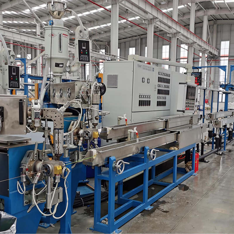
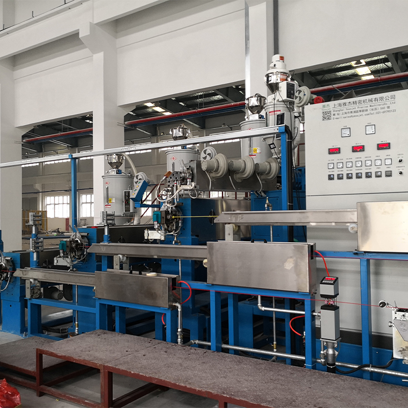 High-Efficiency PP, PVC and PE Cable ExtruderA multifunctional extrusion core for insulation and jackets, compatible with PP, PVC and PE and presented for energy-saving, high-yield cable production.View Product →
Where output has to stay constant through reel changes, temperature stability and line continuity are the same problem. The accumulator and dancer systems for continuous extrusion lines keep the extruder running at a fixed screw speed while the take-up side changes reels, which removes the repeated heat-up and cool-down cycles that cause melt temperature to wander.
Extruder selection deserves its own review before the temperature profile is finalized. Our guide to high-efficiency PP, PVC and PE cable extruders covers screw geometry, output matching and the practical differences between single-machine and integrated line configurations.
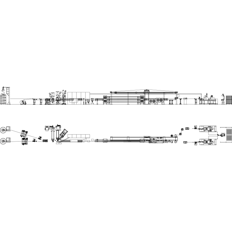 Wire and Cable Extrusion Line for Insulated and Sheathed CableAn automated line for insulated or sheathed wires and cables, combining material-specific extrusion with PLC control and downstream cooling, printing and take-up equipment.View Product →
On the downstream side, melt temperature is only half of the story: the cooling trough and take-up tension decide whether the insulation keeps the dimensions the die just produced. A tension control system that holds within a few newtons prevents the ovality and shrinkage that operators often blame on the extruder.
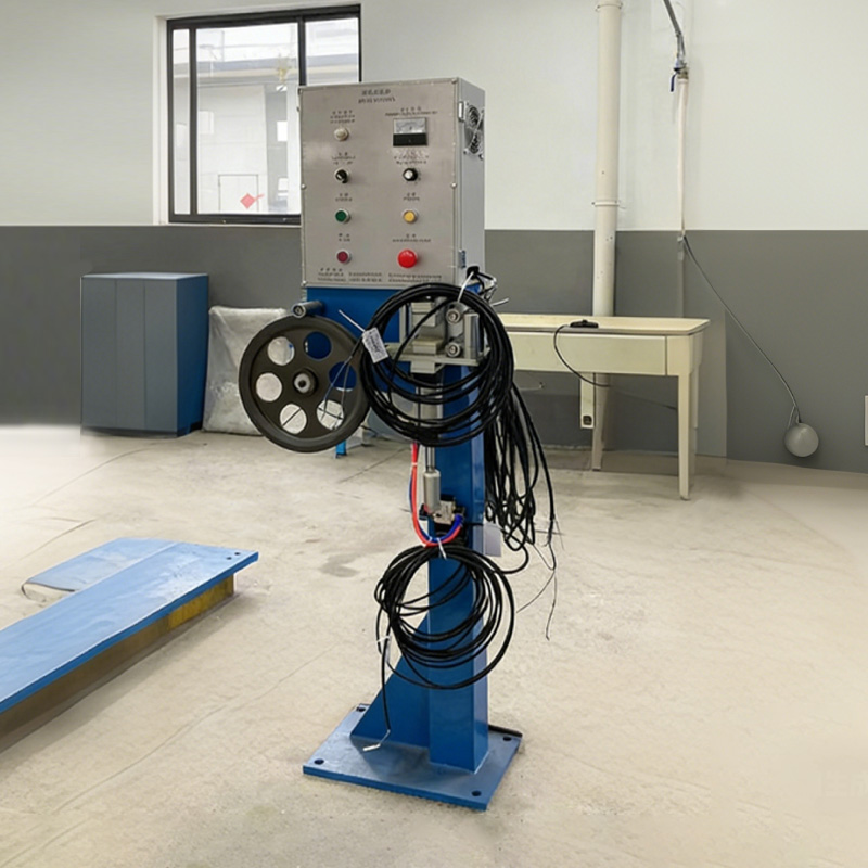 Wire and Cable Tension Control System for WindingAn accessory system that adjusts cable tension in real time during winding to help prevent stretching, damage, loose winding and disordered arrangement.View Product →
Maintenance, Records and Compliance
A temperature window is only as reliable as the equipment around the thermocouple. Three maintenance routines keep it honest:
- Re-tighten heater bands and check contact every quarter; a loose band creates a cold spot that reads correctly at the sensor and wrongly in the melt.
- Verify thermocouples and controllers against a reference probe twice a year, and always after a screw or barrel change.
- Track gel count and screen pack pressure rise per production lot; a rising pressure trend at constant melt temperature usually points to contamination or screw wear, not to a temperature fault.
On compliance, the melt temperature record is part of the process evidence needed for LV cable under IEC 60502-1 and for CPR reaction-to-fire declarations under EN 50575, where the compound formulation and its thermal history both feed the declaration. Keep the melt temperature, compound lot number and reel ID linked in one record; when a customer asks why a batch behaves differently, that link answers the question in minutes instead of days. RoHS and REACH documentation should travel with the compound lot, not with the finished reel alone.
LLDPE will not punish you for running a little hotter than LDPE — it will punish you for running a copied recipe. Treat 120–130 °C as the melting point on the datasheet, 180–230 °C as the processing window on the panel, and 205–215 °C as the practical target for cable insulation. Then verify it with a needle probe at the die rather than trusting the controller display, and write the number down for every reel. That habit alone removes most of the surface, gel and ovality problems that get blamed on the compound.