LANGUAGE
 中文简体
中文简体 русский
 Français
 Español
 Português
 عربى
عربى
Content
The Critical Buffer That Enables Non-Stop Production
A cable storage rack functions as a dynamic accumulator that decouples the continuous process from the batch-based reel changeover. In an extrusion line, CV line, or rewind line, the core process cannot stop: the insulation is extruding, the curing tube is running, or the printing station is engaged. Yet pay-off reels expire and take-up reels fill up, requiring a splice or cut-and-transfer operation. The cable storage rack absorbs this conflict. It accumulates a reserve length of cable—typically 100 to 500 meters for a standard high-speed line—during steady-state running, then releases that stored cable during the seconds or minutes when the pay-off reel is stationary for a reel change. The result is a continuous, uninterrupted linear speed through the process while the upstream or downstream reel stands idle. This single device transforms a batch-dependent line into a truly continuous operation.
Vertical vs. Horizontal Configuration: A Fundamental Choice
The physical orientation of a cable storage rack is not an aesthetic decision; it dictates the space claim on the factory floor, the maximum accumulation capacity per linear meter of floor space, and the cable bending radius that determines conductor integrity. The selection between vertical and horizontal must be made against the specific line layout and cable specification.
Vertical Cable Storage Rack
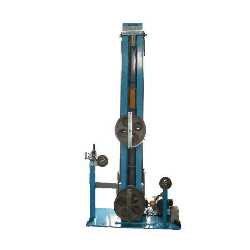
A vertical rack uses height to create accumulation length. Multiple sheaves are arranged in an upper bank and a lower bank, with one bank fixed and the other moving on a linear carriage. The cable makes multiple passes between the fixed and moving sheaves. When the carriage moves apart, the total cable path length increases, absorbing the incoming cable. A vertical rack can store 1.5 to 2 times more cable per meter of floor space than a horizontal equivalent because the separation distance between sheave banks is in the vertical plane. This configuration dominates in facilities with high ceilings but constrained floor space, such as retrofitted older extrusion houses. The critical design parameter is the moving carriage weight, which directly influences the required tension for the accumulator to function without cable slipping on the sheaves.
Horizontal Cable Storage Rack
A horizontal rack arranges sheaves along a horizontal track. This configuration provides lower overall height, easier operator access for threading and maintenance, and a naturally lower moving mass that is more responsive to tension transients. The trade-off is a larger footprint: a horizontal accumulator with a capacity of 200 meters for a 10mm diameter cable will typically require a linear track length of 8 to 12 meters. Horizontal racks are the standard choice for large-diameter power cables where a high vertical carriage weight would demand unacceptably high back-tension, and for clean-room extrusion lines where ceiling-mounted equipment is restricted.
Accumulation Capacity Calculation and Sizing
The required accumulation capacity is not a guess; it is a calculated value derived from the line speed and the maximum reel changeover time. The fundamental formula is straightforward: Accumulation Length = Line Speed (m/min) × Changeover Time (min). A line running at 200 m/min with an operator changeover time of 1.5 minutes demands a minimum storage capacity of 300 meters. A safety margin of 20% to 30% is then added to account for splice failures, operator variability, and the acceleration phase of the new reel. The number of sheave passes required to achieve this length with a given physical stroke is calculated as: Number of Passes = Required Accumulation / (2 × Effective Stroke). A rack with a 5-meter carriage stroke and 16 sheave passes thus provides an accumulation length of 160 meters.
| Line Parameter | Example Value | Impact on Rack Sizing |
|---|---|---|
| Maximum Line Speed | 250 m/min | Defines accumulation fill rate |
| Reel Changeover Time | 2.0 minutes | Determines minimum storage length |
| Cable Outer Diameter | 15 mm | Dictates minimum sheave root diameter |
| Calculated Capacity Required | 500 meters | Basis for number of passes and stroke |
Tension Control and the Moving Carriage System
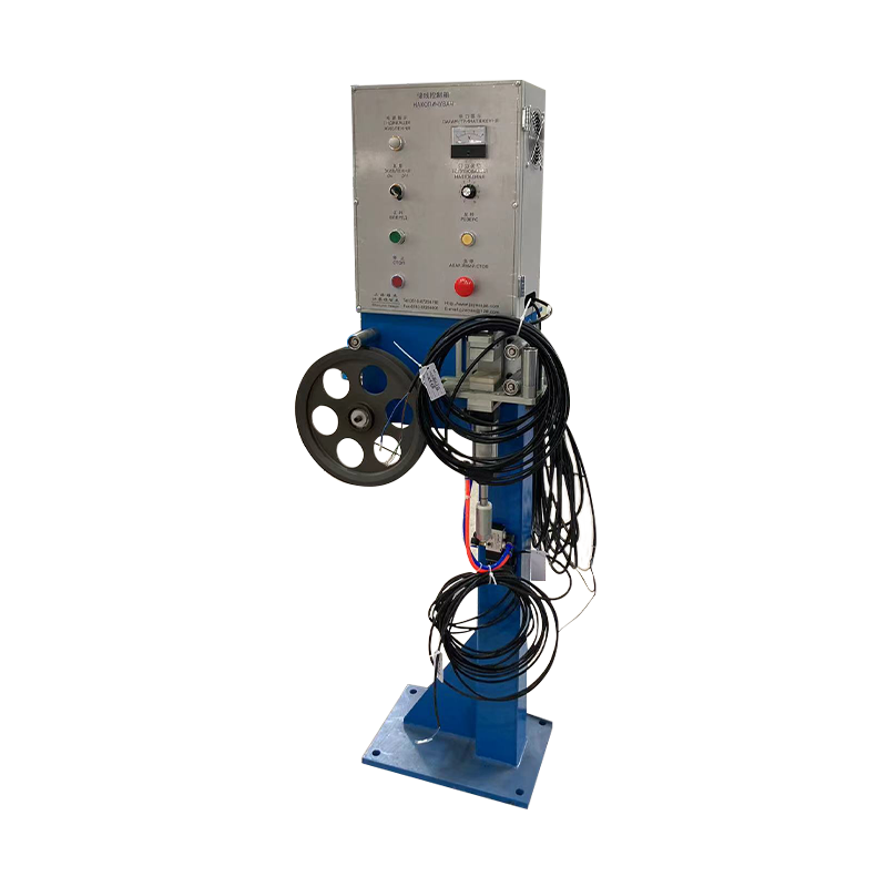
The cable cannot simply be wound loosely around the sheaves; it must be maintained under a precisely controlled tension. If the tension is too low, the cable slips on the sheave, creating surface abrasion and losing the accumulation tracking accuracy. If it is too high, the conductor is stretched beyond its elastic limit, or a fibre optic core is micro-bent, creating attenuation. The moving carriage applies this tension through one of two mechanisms: pneumatic cylinders with a precision pressure regulator, or a servo-motor-controlled torque system. Pneumatic systems maintain a constant tension regardless of carriage position, typically adjustable between 5 N and 50 N for fine data cables, and 100 N to 500 N for medium-voltage power cables. The servo-driven torque system adds the capability to compensate for the changing cable weight on the sheaves as the carriage moves, providing true constant tension that is independent of the accumulated cable mass—a critical feature for long-stroke accumulators on large-diameter cables.
Integration at the Pay-Off and Take-Up Positions
The cable storage rack is positioned between two distinct control zones. On the incoming side, it receives cable from a pay-off stand running at the line's process speed. On the outgoing side, it feeds the constant-speed process entry. During normal operation, the accumulator carriage moves to its "full" position, storing the reserve length. When the pay-off reel is stopped for a splice, the accumulator carriage moves toward its "empty" position, feeding the stored cable into the line. A non-contact position sensor, typically an ultrasonic or laser sensor, tracks the carriage's linear position and outputs a 4-20 mA signal to the pay-off reel's drive controller. This signal commands the pay-off to accelerate or decelerate to keep the carriage centered, creating a closed-loop control that ensures the accumulator is never fully depleted before the new reel is up to speed.
Splice Sequence Without Line Stop
The value of the cable storage rack is proven in the automatic splice sequence. The operator or automatic splicer clamps the expiring cable, cuts it, and butt-welds or tapes the new reel's leading end to the tail of the process cable. During this 90-second sequence, the accumulator discharges its stored cable at a rate of 250 meters per minute into the CV line. Without the accumulator, the CV tube would lose its cable core, causing a full-line shutdown, a scrap section of uncured insulation, and a lengthy re-threading procedure. The storage rack absorbs this downtime and returns the line to steady-state accumulation once the new reel is successfully paying off.
Sheave Design and Cable Protection
The sheave is the only surface that contacts the cable during its transit through the accumulator. For semi-conductive jackets and primary insulation layers, the sheave groove must be contoured to match the cable's outer diameter with a minimum groove root radius of 8 to 12 times the cable diameter to avoid exceeding the cable's specified minimum bend radius. The sheave surface is typically anodized aluminum for light-duty cables, or rubber-lagged for heavy cables to increase the coefficient of friction and prevent slip without requiring excessive tension. In CV line applications, sheaves may be specified with a ceramic coating to withstand the residual heat from the cured cable exiting the tube, which can reach 120°C to 150°C on the cable surface. A single damaged sheave that develops a groove burr will progressively abrade the outer jacket of every meter of cable passing through the accumulator, creating a continuous defect in a kilometer-long cable length.