

 LANGUAGE
 中文简体
中文简体 русский
 Français
 Español
 Português
 عربى
عربىContent
- 1 What Is a Cable Insulation Extruder and How Does It Work?
- 2 Key Components of a Wire and Cable Extruder Machine
- 3 Compatible Insulation Materials: PVC, XLPE, PE, LSZH and Beyond
- 4 Single-Layer vs. Multi-Layer Extrusion: Which Configuration Do You Need?
- 5 How to Evaluate a Wire and Cable Extruder Machine Before Buying
- 6 From Extrusion to Palletizing: The Complete Cable Production Line
Bare copper goes in. Insulated, protected, ready-to-ship cable comes out. The machine that makes that transformation possible is the cable insulation extruder — and choosing the right one shapes every metre of cable your factory will ever produce. This guide covers how these machines work, what their core components do, which insulation materials they handle, and what to verify before placing an order.
What Is a Cable Insulation Extruder and How Does It Work?
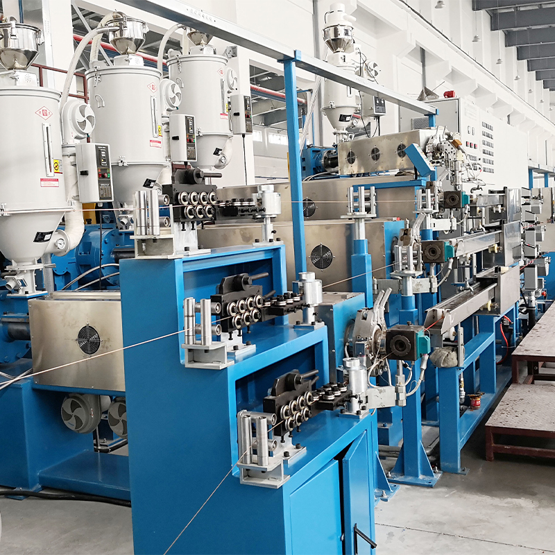
A cable insulation extruder is a machine that melts thermoplastic or thermosetting compounds and forces the molten material around a moving conductor, coating it in a continuous, uniform insulation or sheath layer. The result is a cable that meets the electrical, mechanical, and environmental requirements of its end application.
The process follows four sequential stages. First, raw polymer pellets or granules are loaded into the feed hopper and drawn into the extruder barrel by a rotating screw. Second, friction and external barrel heaters raise the material to its melt temperature — typically between 150 °C and 230 °C depending on the compound. Third, the molten polymer is forced through a crosshead die positioned at a precise angle to the travelling conductor, applying the insulation layer concentrically around the core. Fourth, the coated conductor passes through a cooling water trough where it is quenched and the insulation solidifies to its final dimensions before being taken up on a reel.
The critical performance metrics at each stage are melt pressure, die temperature uniformity, line speed, and cooling rate. Any instability in these parameters — a fluctuating screw speed, a cold spot in the barrel, or an undersized water trough — shows up as wall thickness variation, surface roughness, or eccentricity in the finished cable. This is why modern wire and cable extrusion line solutions integrate closed-loop monitoring of all four process variables from a single PLC interface.
Key Components of a Wire and Cable Extruder Machine
Understanding what each subsystem does makes it much easier to compare machines and identify weak points in a supplier's offering.
Screw and barrel. The screw geometry — its compression ratio, pitch, and flight depth — determines how efficiently the material melts, how homogeneous the melt becomes, and the maximum output rate the machine can sustain. Screws for PVC run a lower compression ratio than those optimised for XLPE; a single general-purpose screw is rarely the best choice for a factory running multiple compounds.
Crosshead die. The die controls the annular gap through which molten polymer is applied to the conductor. Precision machining of the die lips and the ability to make fine adjustments to wall thickness without stopping the line are the two attributes that separate a production-grade die from a commodity casting. Pressure-type dies bond insulation tightly to the conductor; tube-type dies leave a thin air gap, which is preferred for some data cable constructions.
Cooling water trough. Cooling length and water temperature directly set the maximum line speed. A trough that is too short or runs too warm forces the operator to slow the capstan to avoid deformation of the insulation — cutting throughput and raising cost per metre.
Capstan and tension control. The capstan pulls the cable through the die and trough at a controlled speed. Precise, jerk-free tension control is essential; any surge transmits directly to the die gap as a change in insulation wall thickness.
PLC control cabinet. A well-integrated control system allows the operator to set target parameters — zone temperatures, screw speed, line speed — and have the machine maintain them automatically. Alarm logging, recipe storage, and remote diagnostics are now standard expectations on any production-grade extruder.
Compatible Insulation Materials: PVC, XLPE, PE, LSZH and Beyond
The extruder's screw design, barrel temperature profile, and die geometry must all be matched to the insulation compound being processed. These are the materials you will encounter most often.
PVC (Polyvinyl Chloride) is the industry workhorse. It processes cleanly on standard single-screw extruders, tolerates wide temperature windows, and suits building wire, flexible cords, and control cables. Its ceiling is roughly 70 °C continuous operating temperature, and it releases hydrogen chloride when burned — a limitation that has driven the adoption of alternatives in confined-space applications.
XLPE (Cross-Linked Polyethylene) operates up to 90 °C continuously and handles 250 °C short-circuit conditions, making it the dominant insulation for medium- and high-voltage power cables. Cross-linking is typically achieved with peroxide compounds added at the compounding stage; the extruder must maintain precise temperature profiles to prevent premature cross-linking in the barrel.
PE (Polyethylene) — low-density (LDPE), high-density (HDPE), and linear low-density (LLDPE) grades — is the preferred insulation for data and telecommunications cables where a low dielectric constant is critical. PE requires tighter melt temperature control than PVC because its processing window is narrower.
LSZH / HFFR (Low-Smoke Zero-Halogen / Halogen-Free Flame Retardant) compounds are mandatory in tunnels, rail, marine, and public building applications where toxic smoke from a cable fire poses a life-safety risk. These compounds are abrasive, have higher melt viscosity, and demand screws with appropriate wear protection and higher torque drives.
Other materials — TPU for flexible automotive harnesses, TPE for consumer products, and ETFE or FEP for high-temperature aerospace wiring — each bring their own processing requirements. The safest approach before purchasing a machine is to confirm with the supplier that the screw and barrel combination has been validated for every compound in your product range.
Single-Layer vs. Multi-Layer Extrusion: Which Configuration Do You Need?
Entry-level cable production commonly starts with a single-extruder line: one screw, one die, one insulation layer. This configuration handles the vast majority of building wire, flexible cord, and single-core control cable at competitive cost. Line speeds for single-layer PVC insulation on a 1.5 mm² conductor routinely reach 200–400 m/min on a properly sized machine.
Multi-layer extrusion becomes necessary when the cable design requires differentiated functions across its cross-section. A semi-conductive shield beneath the main XLPE insulation layer of a medium-voltage cable, for example, cannot be applied in a separate pass without risking inter-layer contamination; it must be co-extruded simultaneously. Similarly, dual-colour insulation for polarity coding in automotive wiring requires a tandem or dual-head arrangement.
The three practical configurations are tandem (two extruders in series with independent dies), dual-head (two extruders feeding one die at separate entry points), and triple-head co-extrusion (three extruders, one die, used for semi-con / insulation / semi-con layers on HV cable). Each step up in complexity adds capital cost, demands tighter process synchronisation, and raises the skill level needed to set up and troubleshoot the line.
Before specifying a configuration, map your product portfolio against these requirements and size the machine for your peak output demand, not your average. The available range of cable extrusion machine configurations — from single-screw units through multi-layer co-extrusion lines — covers the full spectrum of these requirements.
How to Evaluate a Wire and Cable Extruder Machine Before Buying
Price is rarely the variable that determines whether a machine purchase was a good decision. The real drivers are uptime, output quality consistency, and the cost of support when something goes wrong. Here is a practical checklist.
Output rate and conductor range. Confirm the maximum line speed and the conductor size range the machine is rated for. Ask for validation data, not nominal specifications — a machine rated to 300 m/min but tested only at 150 m/min in factory acceptance is a commercial risk.
Temperature control precision. Each barrel heating zone should hold setpoint temperature to ±2 °C or better under production conditions. Wider variation produces inconsistent melt viscosity and, downstream, inconsistent wall thickness.
Screw material and wear protection. For abrasive LSZH or filled compounds, ask whether the screw and barrel are fitted with bi-metallic liners or surface hardening. Replacing a worn barrel on a production machine is expensive and time-consuming.
Certifications. CE marking confirms the machine meets European machinery directive requirements. For markets requiring UL compliance, verify that the supplier's equipment carries recognised third-party certification. Machines certified by authoritative bodies reduce the risk of issues at customs or during customer audits.
After-sales support model. Find out where spare parts are stocked, what the typical lead time for a screw or heater band replacement is, and whether the supplier offers remote diagnostics. A machine that sits idle for three weeks waiting for a spare part will have erased its purchase-price advantage many times over.
Factory acceptance test (FAT). Insist on a witnessed FAT running your specific material and conductor. The test should demonstrate continuous production at target speed, wall thickness within tolerance, and stable temperature profiles across all zones. Any deviation from agreed parameters should be corrected before shipment.
From Extrusion to Palletizing: The Complete Cable Production Line
An extruder in isolation produces metres of cable that pile on the floor. The upstream and downstream equipment around it determines whether those metres become a profitable, shippable product.
Upstream, a motorized pay-off and take-up equipment feeds conductor from a supply reel at constant, jerk-free tension into the extruder crosshead. Any variation in pay-off tension creates a corresponding variation in conductor position within the die — and ultimately in insulation eccentricity.
Downstream, the insulated cable must be measured for diameter and wall thickness in real time, printed with identification markings, cut to length, and coiled or reeled for shipping. Fully automatic coiling and packaging systems handle this final stage without manual intervention, reducing labour cost and the risk of damaged or mis-labelled coils reaching the customer.
At the end of the line, an intelligent robot stacker palletizes finished reels or coils at throughput rates that manual handling cannot match, completing the automation chain from raw conductor to pallet-ready product.
The economic case for treating extrusion as part of a complete line rather than a standalone machine is straightforward: a high-speed extruder throttled by a slow manual coiling station, or a precision die head fed by an inconsistent pay-off, cannot deliver its rated output or quality. Matching every station's capability to the line's peak throughput is how planned production capacity actually translates to shipped product.
Yessjet designs and supplies the full sequence — extrusion line, pay-off, take-up, automatic coiling, packaging, and palletizing — as an integrated solution. Explore our turnkey cable plant planning services to see how a complete line is engineered around your product range and output targets.


